Refer to your S-160 instructions
Drawing No. 3 Locomotive Superstructure.
"STEAM LOCOMOTIVES PROJECTS & IDEAS" by John Pryke from Kalmbach Books.
I find it an excellent reference for building and kit bashing steam. Particularly those sections dealing with plumbing and mounting appliances. Always use a mechanical pin or screw in addition to solder and or adhesives if you can.
To describe parts I will use the "English term" part number and the common "American term". to introduce the part and from then on use only the American term.
Decision time: Before you start work on the Boiler and Cab, look at the photos of your prototype and determine where appliances are going to be located. Make an extra copy of drawing 40-67 and 68-74 and sketch in where you are going to install the following items.
Mark these components on the drawings and white out those mounting holes you will not be using. Note there is a dimple just above the center line at the right rear side of the smoke box for a large line that is nonexistent on ARR locomotives.
Use sharp #76 drills with short repeated plunging strokes in the Pewter casting to pilot drill the holes you will need. Repeatedly clean the drill bit and if it binds do not twist it. Disconnect the chuck and use a pair of pliers and pull the bit straight out of the hole. You can enlarge the holes later to mate the appliance or pipe at time of assembly. I over size these holes so there is a place for the flux/solder or Black Rubber ACC to work and for adjustment of the part.
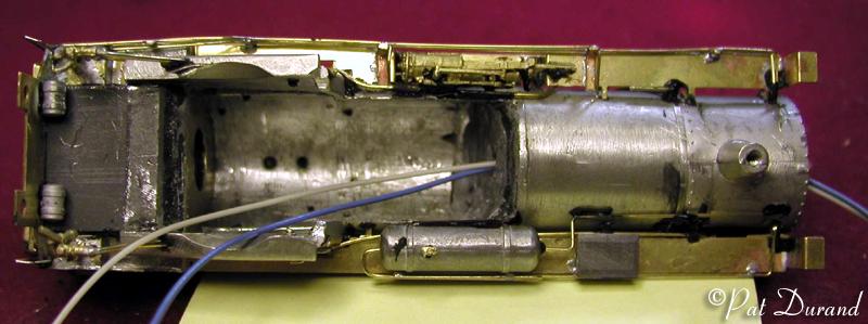
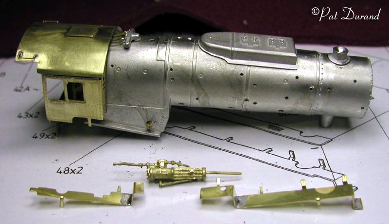
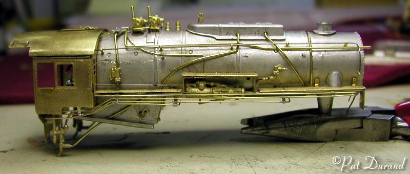
Decision time: If you want to work your locomotives they need to be heavy, so now is the time to commit to adding weight where ever you can and consider how this will relate to features such as lighting and servicing. A typical installation shows the boiler after the cab has been attached along with additional lead weight. 16 gauge lead sheet has been rolled into a tube and inserted in the boiler space extending within 3/8 inch of the smoke box front. A small plastic tube conduit was extended through the middle of the weight for headlight wires. Additional lead was added under the cab floor and inside the back head casting in the cab. A hole has been drilled into the brass front of the cab behind the back head to allow added clearance for the end lash in the motor shaft. The signal flag box under the left running board is also made of sheet lead. The finished locomotive weighs 14.6 ounces on the drivers. There is still room inside the cab roof for another layer of lead which can be scribed to resemble the wood lining. The weight is all attached using JB Kwik. If you add the weight early on then all the appliances, pipes etc. can be drilled and mounted right through the brass and into the lead.
Take the time to pilot drill all the brass fittings for pipe connections while they are still on the sprue with #76 or appropriate drill. They can be enlarged as required but this first step will save you a lot of frustration later.
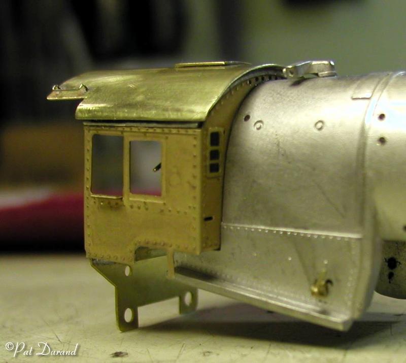
The kit is faithful to the spartan cramped military cab of the prototype. Look at your prototype photos and study the height of the cab roof over the top of the boiler and the width of the cab front at the running boards. 560 and 556 for example had the entire cabs rebuilt wider with a splice piece welded in that moved the original cab side outward by 8 inches on each side for a total width of 122 inches. The arch of the roof was increased to extend up to 18 inches over the backhead and a new welded roof was formed up and welded in place, ie no rivets on the roof.
How high the cab is varies with each locomotive so you are on your own here. A new sheet brass cab roof can be fabricated to the proper arch and applied over the old pewter roof with spacers using JB Kwik.
If you are going to widen the cab, cut the photo etched cab
#41 in half down the middle before bending the seams. When the final width
is determined, solder a brass splice in and use the pewter boiler backhead
casting #45A to join the two halves together. Cut the pewter roof #44 down
the middle, and use two pieces of sheet lead, one 16 inches wide to fill the
space and another the width of the cab on the inside , to splice the two halves
together (take every opportunity to add weight). JB Kwik is the right adhesive
for this job. Remember the top of the roof can be up to 18 inches above the
backhead.
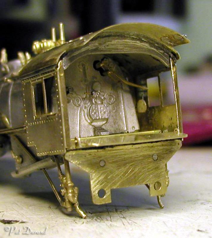
The kit provides no rear wall in the cab.
You can add a back wall to strengthen the assembly using this photo of the
rear of #557 as a guide. If you do not create your own wall then you can install
the cab roof support #47 for the stock cab.
If you do opt to extend the cab to 122 inches wide there is a rear wall section 31 inches wide on each side. This leaves an arched opening 60 inches wide and 74 inches high. There is a single pane window on each section of the back wall that measures 24 inches high and 18 inches wide.
Dry fit the cab to the boiler for now, as you will want to drill holes in the face of the cab for the turret valve handles, blow down operator rods, whistle and bell cords once these items are located on the boiler.
The window beading #43 is only used if the windows are to be closed. I do not use them as I model the windows in the open position, slid forward.
Running Boards are composed of two parts. #48 Footplate valance Plates are the foundation and #49 Footplate proper with the tread. These are very nicely engineered components and I suggest you install the left side as per the instructions as practice. I soldered parts 48 and 49 together by fluxing and tinning the mating surfaces. Then add more flux, clamp the parts together with several aluminum alligator clips or wood clothespins and apply heat and solder from the tip of the iron along the back seam edge of the two mated pieces. They will flow together.
The Right Side Running Board needs to be modified with a step up to clear the Power Reverse. Here are the dimensions for making the adjustments: 8 feet from the cab there is a 16 inch step up. Next is a 6 foot 7 inch tread and back down 16 inches. This leaves a section 9 foot 9 inches long to the next step down. By cutting part #48 at 12 feet from the cab you can bend the step up on the cut end of each piece and then add a splice between the two halves once they are pre positioned and fitted to the boiler casting.
Part #49 can then be cut in three pieces to complete the tread surface of the Right Side Running Board. Some filing is needed to reduce the width of the stepped up portion of the running board. You may want to add additional braces under the running boards for support and to hang pipes, by drilling into the boiler and inserting more wire supports.
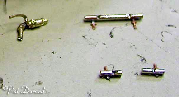
The Power Reverse is modified as shown in the photo by removing the valve operating rods from the front and soldering them on the back side. Position the power reverse casting and drill into the boiler to accept the locating pin. There is plenty of space behind the appliance to add extra JB Kwik or Lightning ACC and filler beads to firmly affix this large piece.
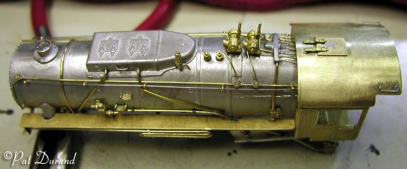
The Steam Turret #51 and Safety Valves #52 are plumbed directly to the boiler. They look funny if you just plug them into the holes because there is no accommodation for the 4 inch thick boiler lagging that surrounds the boiler. Easy step to improve the appearance is to counter bore into the boiler about 1/32 of an inch to clear the base of these appliances. Now when you install them they snuggle down and appear they are recessed in holes in the lagging and jacket. When mounting the steam generators, cut a notch in the "lagging" so the bracket under the generator appears recessed. This also makes them stronger.
Fit and install the steam turret and sand box #55. Do not use either whistle 50 or 54. The proper whistle is Precision Scale #3100 and it is modified as shown in the photo. The Chimney #56 or smoke stack varies loco to loco. If you are going to extend the stack, find the right size tubing and then drill out the flange on the Chimney #56 to fit the tubing. Allow the stack material to extend below the flange about 1/16 inch and drill out the hole on top of the smoke box to accept the new stack and flange. the rim around the top of the stack can be fabricated with the next size of tubing or a piece of wire bent into a loop and expanded around the stack and soldered or fixed with gap filling acc.
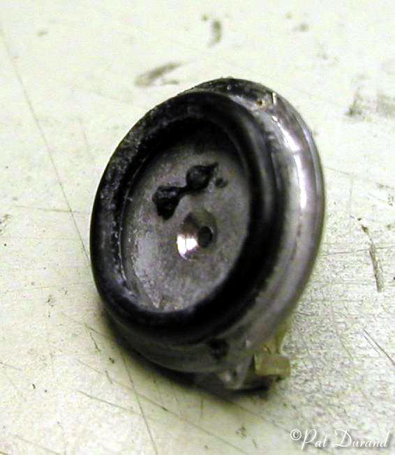
Clean the smokebox front 59A until it is an easy fit. Square the front cover and the smoke box up and then at the bottom of the smoke box scribe a registration mark to match the smoke box front. If you plan to light the head lamp, keep the smoke box front a separate piece by gluing one or two 18 mm rubber O rings on the back of the Smoke Box Front casting with Lightning Bond ACC. Let this cure overnight and then press into place in the smoke box without adhesives.
Prepare both air tanks #61 by drilling into the center of each end to accept 1 3/4 inch pipe. Mount the tank on the left side under the running board and glue it securely to the side of the boiler with JB Kwik or Lightning ACC and filler beads. The tank on the left, and power reverse on the right and the attendant running boards will take a lot of abuse. This is where most people will pick up the locomotive so build it strong. Set aside the second air tank as it will be installed above and between the frame rails of the chassis under the boiler.
Drawing No. 4- Details and Pipes.
As you observe prototypes look for mechanical fasteners on pipes and appliances and try to duplicate them. The main feed water line from the injector to boiler check can be fixed to the boiler side with one of the small soft metal cotter pins looped over the pipe and inserted into a hole in the boiler side. You can make similar fasteners for smaller pipes with brass wire pulled through holes to the inside of the boiler casting to the inside where they are glued or soldered.
I use only .010 and .015 steel wire for hand rails and grab irons. It holds its shape and when the paint comes off you see steel not bright brass. The variety of brass wire included is more than enough to plumb the locomotive.
A field trip to locomotive #556 on the Delaney Park Strip in Anchorage resulted in over 100 photos and some basic measurements for modeling. Here are some of the details to help you select the proper wire sizes.