In your DJH S-160 instructions refer to Drawing No. 5 and Chassis Assembly guidelines.
These are excellent instructions as far as they go. You will notice that some of these parts are photo etched and then some openings are stamped out. The axle journal openings for example may have been slightly bent in this process. Place these flat parts in a smooth jaw vice and flatten them. If necessary use a small hammer to lightly tap them into a flat plane. Then test fit your previously assembled axle and wheel assemblies into the individual side frames to make sure they are a smooth running fit.
While the frame rails #82 and 75, are still in the flat, polish them on a surface plate or piece of glass plate covered by a section of 600 grit or finer emery paper. You will find out if they are flat, and clean all the surface oil and contamination off so they will easily solder after assembly.
Carefully file and fit each of the spacers #78X3, 79 and 80 and note their unique positions. They must fit and set square between the frame rails. Polish these as well to accept solder.
Now bend the motor support and rear frame tabs and test fit the assembly with the spacer blocks 76 and 77. Remove the screws from the left frame rail and insert the spacers mentioned above and then secure with screws . When this assembly is all square flux each bend and the ends of the spacers where they extend into the side rails. Pick up a small amount of solder on your 20-30 watt tip and flow solder into the joints.
We covered the wheel axle and journal bearing assembly in Section 4 of this construction series. Polish the ends of bushings 83 and 85 and assemble with gear 84 on shaft 86 per the instructions with the shorter bushing 85 on the left. Fix shaft 86 on the right end with tire glue applied from the outside of the frame rail.
Install the rear driver with gear so it meshes with the idler gear and test for smooth operation and alignment. Install the other wheel sets in the frame and roll the assembly on a surface plate or plate glass. When all is free rolling check to make sure that the driver gear and the idler gear properly mesh. If not you will need to remove some material from the top arch of the journal box hole on both sides of the frame. Keep fitting this gear assembly until it has proper engagement. Now remove the same amount from the other 6 journal holes and assemble the drivers for another test to make sure they all contact the rail or surface plate evenly.
Decision point, If you plan to install DCC:
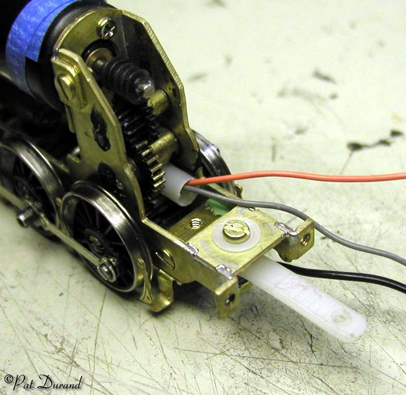
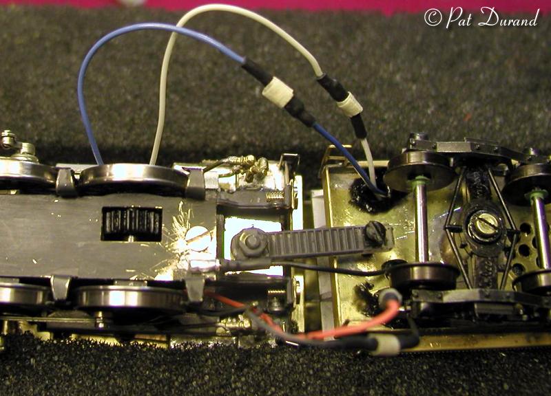
Disregard the brass drawbar parts 95 and 96 and replaced it with one made from a piece of nylon tie strap. Use the same hole spacing. Continue the draw bar assembly leaving out electrical wire #93. Replace the tender drawbar post with a 1/2" long 256 screw so the locomotive and tender are joined. If you tap the drawbar hole in the tender 256 then the screw will bottom out on the underside of the firing deck. The whole locomotive and tender assembled is small enough to pick up in one hand.
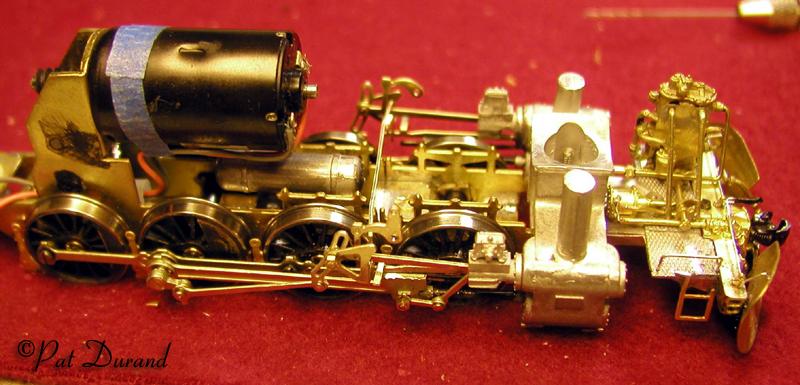
If you are using only DC power then follow the kit plan instructions. Install and test the motor for proper alignment.
Refer now to Drawing No. 6 Mechanical Workings and Connections.
Form the keeper plate 109 and install it per the instructions. If you had to adjust the rear driver vertically to get proper gear mesh then some small adjustment is needed on the keeper plate. Install shims as needed between the keeper plate and the journal holding the rear axle in the frames. The shim can be soldered to the top of the keeper plate and final adjusted with filing. The other three axles can float. At this point remove the motor and secure the keeper plate. Test for free rolling on the surface plate. All drivers should touch the plate and roll freely. If not find out where the bind is NOW.
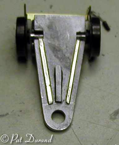
Assemble the front bogie body 144 (lead truck) with a little modification. If you plan to have flangers add them to the guard Irons 143. If not discard part 143. It is a good idea to reinforce the pilot truck with two splines of brass strap glued to the back side.
At this point, jump ahead to fitting the sub radius rod assemblies 126. It is much easier to make adjustments without the crosshead guides and the valve gear in the way. Start by fitting the rods over the main crank pin on the third driver and then install on to the rear driver with crank pin screws 113. Roll to test for free movement. If there is resistance carefully ream the holes in the side rods, one hole at a time and keep testing for free movement. Then add the second axle and finally the first axle and repeat the testing until you have a free rolling assembly with the side rods all bolted up. Reinstall the motor and run it for about an hour alternating forward and reverse with liberal lubrication of the axles and rods.
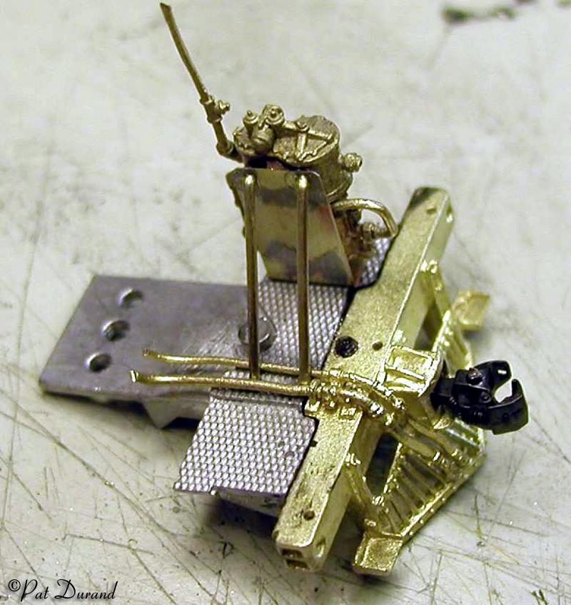
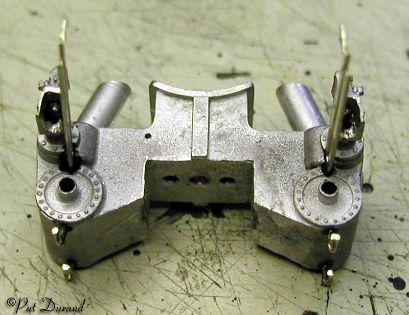
Now go back to working on front footplate 114 (pilot deck) and the cylinders 120 as an assembly. Use tire glue to install the valve crosshead guides 122 into the cylinder casting. This is a good time to install the automatic cylinder cocks made by simply soldering a piece of brass wire to the kit part 121 and separating them.
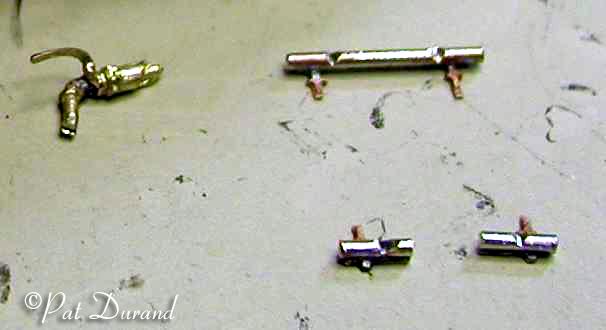
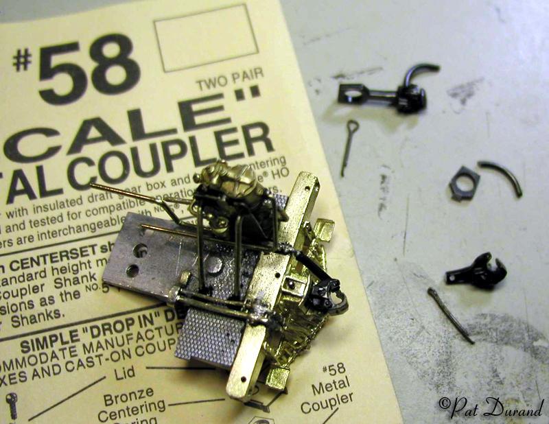
There is not room for a full coupler draft gear on either the prototype or the model. Use a Kaydee #58 coupler with the draw bar cut down. Position the short draw bar into the brass pilot beam casting and drill a #78 hole though from the top center of the pilot beam draft gear box down through the coupler draft bar. Install one of the small cotter keys as a coupler retaining pin.
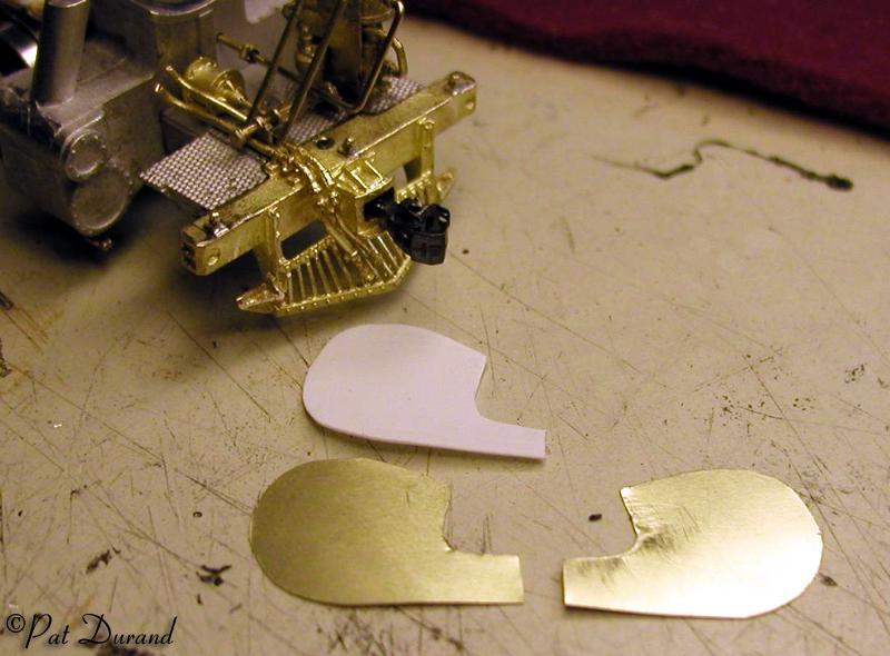
Decision time: With our without snow plow?
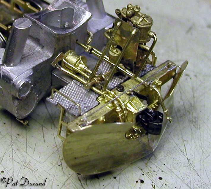
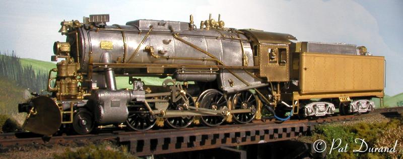
The snow plows are a little tricky, but I have a basic template from which these can be built in brass. With loco 556 in the park I was able to divine how they did the plow mount. The bottom of the plow is on 4 inch spacers in front of the tube pilot and welded in place. That's how I build it. After forming and joining the two plow halves, solder it on to the bottom edge of the Cal Scale pilot casting with spacers in place and then finish form and file it to shape. Do this before you attach the Alaskanized brass pilot beam to the white metal parts. Each one is different and the pieces were flame cut so 90 degree file marks on edge are appropriate.
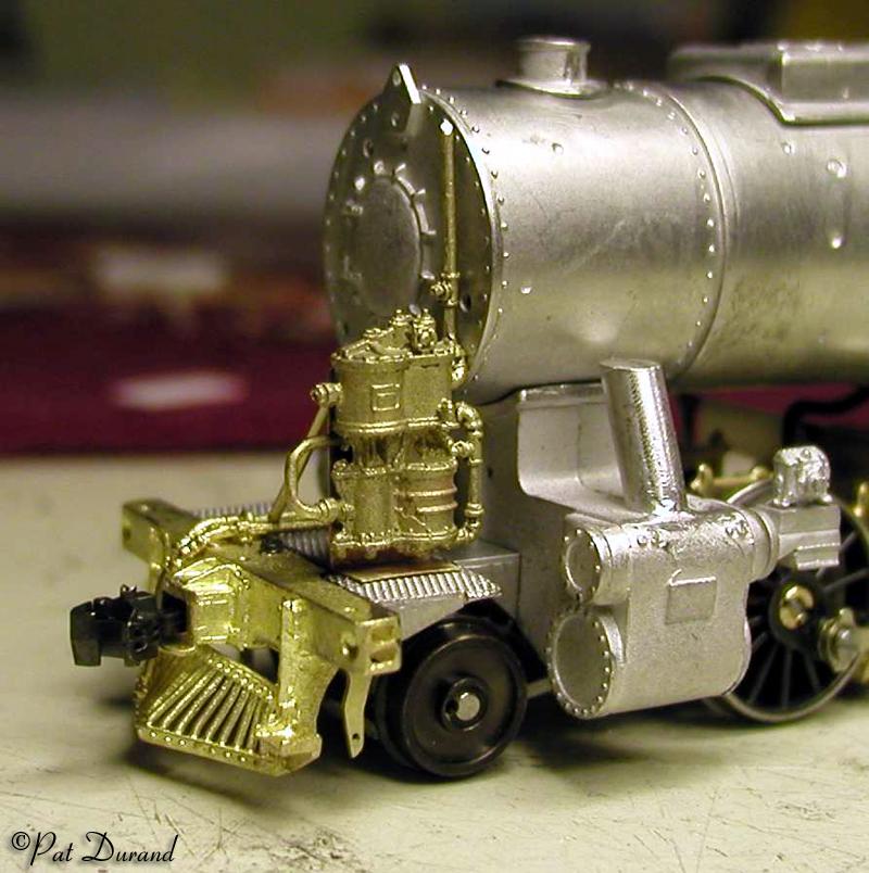
Apply the brass pilot beam with or without the plow after fitting it to the front of the white metal pilot deck. Mount it flush with the top of the pilot deck. Make up the bracket for supporting the Compound Westinghouse Air Pump on the Pilot deck. Add the plumbing so the pump exhaust goes into a hole in the front of the cylinder saddle. Other pipes should disappear under the running boards.
Drawing 109-149 shows only the right side of the valve motion so be sure to wrap your mind around the inverse assembly of the left side. Polish all the mating surfaces of these small parts, it will pay off in the long run. The piston rods and crossheads 127 can be a little rough so take the time to clean them out and make them smooth running in both the cylinder packing gland and on the slide bar guides 124. When installing the slide bar guides you will need to remove a small section of the cylinder casting to allow the bar mounting pin to bottom out against the cylinder casting. Secure the bar guides with tire glue and ensure they are perpendicular to the cylinder block so they are maintained parallel to the frame.
Finish installing all the valve motion and test run the locomotive while observing and adjusting any resistance points. When the boiler and cab are mounted on the chassis you can add the two steam pipes 60 in proper alignment above the running boards between the stack and the cylinder exhaust lines.
If upon operation there is any motor noise it is likely coming from the back end of the motor shaft touching the brass front of the cab inside the firebox. Drawing 40-67 shows a clearance hole in part 41 at this location but it did not make it in production. Use an abrasive cut off disk to grind away or cut a clearance space for the motor shaft and the noise will go away. Under straight DC operation and with quality DCC decoders the drive train is very quiet.
You can add weight at several locations on the chassis. About 1/2 oz can be added between the frame rails while maintaining clearance from the axles and journals. Another layer of sheet lead fits under the pilot deck where a front frame extension and draft gear would normally be just ahead of the steam chest. With 14.8 oz on the drivers there is still power to spare with the drivers slipping.
I hope to see a large fleet of these HO scale S-160 locomotives built around the world. That would be a fitting tribute to the largest single class of steam locomotives ever built. If these notes can help inspire some builders I will have meet my goal.
A large stock of the American details in the parts list is on hand. If I may be of personal assistance feel free to contact me. Please send me photos and progress reports on your S-160 projects. I would like to see some Korean, Chinese, English and European versions as well.
Patrick J. Durand