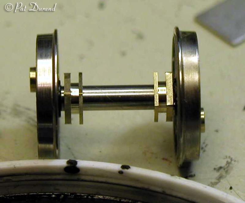
This section jumps out of sequence all the way to drawing 5 in your instruction sheets. While the boggie wheels and pilot wheels all check at a perfect back to back of 14.5 mm for HO scale, my experience has been the driver assembly tends to be narrow in the back to back measurement by up to .5 mm. This is a most important measurement because if the back to back is too narrow the drivers will not negotiate frogs and turnout points properly.
So get them assembled and checked now, not later. Then we can fix the problem or if it is severe you can request replacement insulated drivers. Get your HO NMRA wheel gauge handy.
About half way through the instruction for Drawing #5- Chassis Assembly you will come to: "Fit the insulated and live driving wheels (99 and 104) with balance weights." This is where we part company with the very brief instructions and forget the etched brass counter weights for now. There are a lot of issues that need to be carefully addressed at this point.
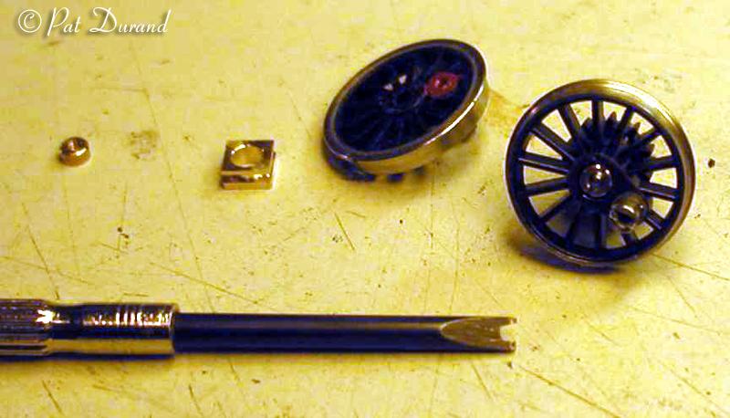
Locate the four IS (Insulated Drivers) and physically check that they are insulated by checking for continuity between the tire and the wheel center. There should be NO continuity in the IS driver. Now take a drop of RED paint (Right Side) and paint the crank pin hole end exposed on the inside of the IS Drivers.
Locate the four LS (Live Drivers) and physically check that they are conductive from the tire to the wheel center. The Isometric drawings are great but some folks have a hard time visualizing the opposite side of the assembly, all parts for which are not shown.
Locate the 8 bushes (103) which are actually the axle bearings and journal all in one piece. Take note that there are thick and thin flanges on each bush. Pay particular attention to installing these on the axles so the THICK flange is always closest to the back of the driver. The thin flange will ride inside the frame rails 82 and 75 at final assembly.
Locate the 8 axle fixers (102) which are the spanner nuts that hold the drivers to the axles on each end. Make your self a spanner driver out of a small screw driver. Grind or file a notch in the end of the driver blade to clear the threaded axle with ears extending to engage the slots in the spanner nut and still fit into the recessed hole in the face of the driver.. This tool will save you a lot of aggravation, so make a good one.
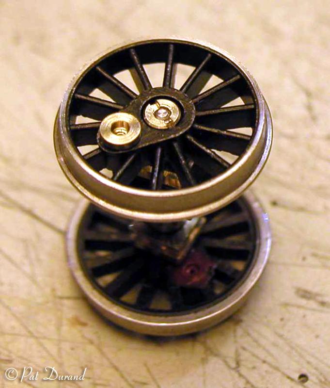
Start with the 3rd driver set which will be assembled using the two drivers with the main crank pins that are factory installed. Use a plain axle (100) and slip the LS driver with crank pin over the shouldered end to be secured with one spanner nut. Take the nut down snug and check that the wheel back and the axle are square and that no gap shows on the back side of the axle shoulder.
Now slip the two bushes on the axle noting the proper location of the thick flange facing outward at each end of the axle. Install the IS driver with the crank pin observing the left lead of the RED right side driver by 90 degrees. When the LS driver crank pin is facing forward, the IS driver on the RED side should be pointing down 90 degrees in advance (lead). This orientation of bushes (bearings and journals) and crank pins should be maintained through out the assembly process.
Here is the first check point. Roll the assembly across the table and note if the two drivers are parallel and not wobbly (discounting of course the crank pins and resulting counterweight effect). Now check the back to back and flange measurement with the NMRA standards gauge. If wide gauge carefully tighten the spanner nuts and check again.
If the back to back is narrow gauge loosen the spanner nut on the IS or RED side 1/2 revolution, then pull that driver out on the shouldered axle and gauge again. Use a little ACC applied with a pin to the crack between the axle shoulder and the back of the IS RED driver. (Make sure you do not glue the bearing journal to the axle.) As the ACC (Mikes) is curing check the gauge all around and roll the assembly looking for wobble. Keep playing with the nut and wheel set until it runs true, add a little more ACC to the crack with a pin and set it aside to cure over night.
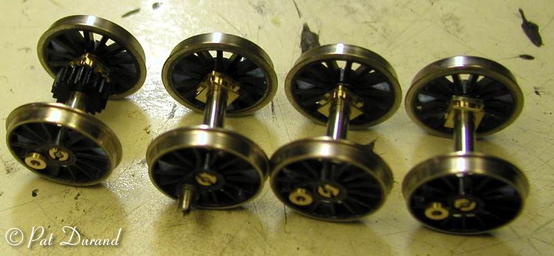
The fourth driver assembly gets the same treatment when mating the drivers, bearings and the geared axle (101). Note the long shoulder of the geared axle goes to the IS or RED right side of the assembly.
I do not install the axle covers (108) as they would interfere with later repairs or alterations. You can now add the counter weights (balance weights 105, 106 and 107). Remember these are to counter balance the weight of the main rods and drive rods, so they will be centered directly across from the crank pin holes. The largest will go where both the main rod and connecting rods come together on the third axle. The next largest (105) go on drivers two and four. The light weight (107) go on the front driver which carries only the light end of the drive rod. I used a file to clean and rough the back side of the etched brass counterweights and then coated them with the black TIRE GLUE. I then dabbed TIRE GLUE onto the spokes where the weight will go and finally mate the two pieces. Give it a squirt of accelerator once the counter weight is positioned properly away from the tire edge and the insulation surrounding the wheel.
If you have an insulated driver that is defective and cannot be brought into gauge then follow the kits special instructions for obtaining a replacement part direct from the kit manufacturer.