A committment to building a particular prototype locomotive or selecting the features you want in the finished model is the starting point. The S-160 Consolidation Kit will build the locomotive as delivered to the U.S. Army Transportation Corps for shipment to Europe.
The 12 locomotives sent to Alaska were modified on arrival with American appliances. Review of photos has resulted in a parts list of available brass and white metal components. All these items are stocked by Roundhouse Hobbies for immediate shipment. If you need assistance in selecting components for your prototype refer to the list and contact me.
Only open the plastic bubble package for the parts required
on demand. Use your parts tray to organize the parts once they are out of
the plastic bubble pack.
Drawing No.1 Assembly of the Tender Body
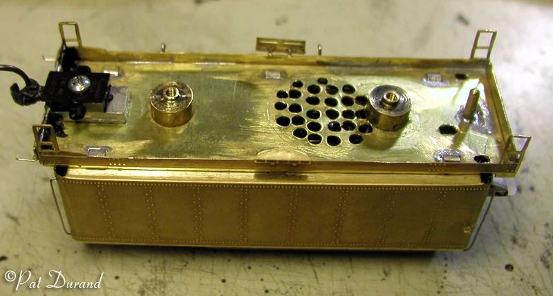
Decision Point: Do you plan to add sound and DCC functions? If so, you will want to drill holes in the footplate (1) sheet before you begin bending it to shape. Match the shape of your speaker with a series of 1/8 inch holes centered between the two boggie pivot (19) (Bolster) holes. Also gang drill two 1/8 inch holes just forward of the front bolster location on each side of the tender floor to allow extra wiring for DCC. Reference photo for details.
Continue with instructions: When bending the tender components, use the jaws on your bench vice to hold the short leg of the bend. These etched joints bend very neatly. Make all the 90 degree bends first and then the rounded corners. Use a piece of tubing either brass or styrene to back up the round corners as you bend them. When all the tabs are inserted and the foot plate and tank sides and back (2) are square, reach in with a brush and apply acid flux to all the mating surfaces and the bent corners. Pick up a small dot of solder on your tinned chisle point tip and touch each joint and corner on the inside. Make sure to have all the sole bar (4) tabs fully inserted when you touch the solder to them from the inside. NOW WASH THE FLUX OFF WITH WARM BAKING SODA WATER AND A TOOTH BRUSH!
Forget the coupling pin (16) and move on to prepare the now assembled tender frame for the coupler of your choice.
Decision Point: To install Kadee #58 couplers with draft gear, you will need to file a notch in the buffer beam (5) where it is soldered to the footplate (1). File a notch to the draft gear width until there is only 1/16 inch of the buffer beam extending below the bottom of the footplate. Eventually you will use a styrene spacer to fix the final coupler height. Now break out the Tire Glue (see adhesives section) as this is the adhesive of choice for joining all the white metal parts of the tender. Clean all the white metal parts with warm soap and water and a tooth brush to remove parting agents and oil.
Decicion Point: Do you want an oil or coal fired locomotive? Only 557 operated on oil in Alaska during the last 10 years on the roster after coaling facilities were closed. Select either the coal hopper or oil bunker and associated front. I will proceed as if the decision was made for coal.
To accomodate DCC and sound, the top (7) (tank deck) and the two top supports (6) along with the hopper sides (8) hopper back and tool box (9/10) and water filler (30) will all be glued togehter with the Tire Glue or epoxy of your choice. This will be maintained as a separate assembly which will be removable from the tender tank. It will form a press fit with about 1/32 inch of the brass tank side extending above the top tank deck. You may want to file down the bottom of the top supports to get the desired reveal around the top of the tank deck.
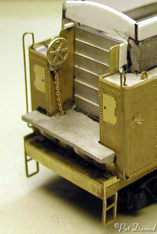
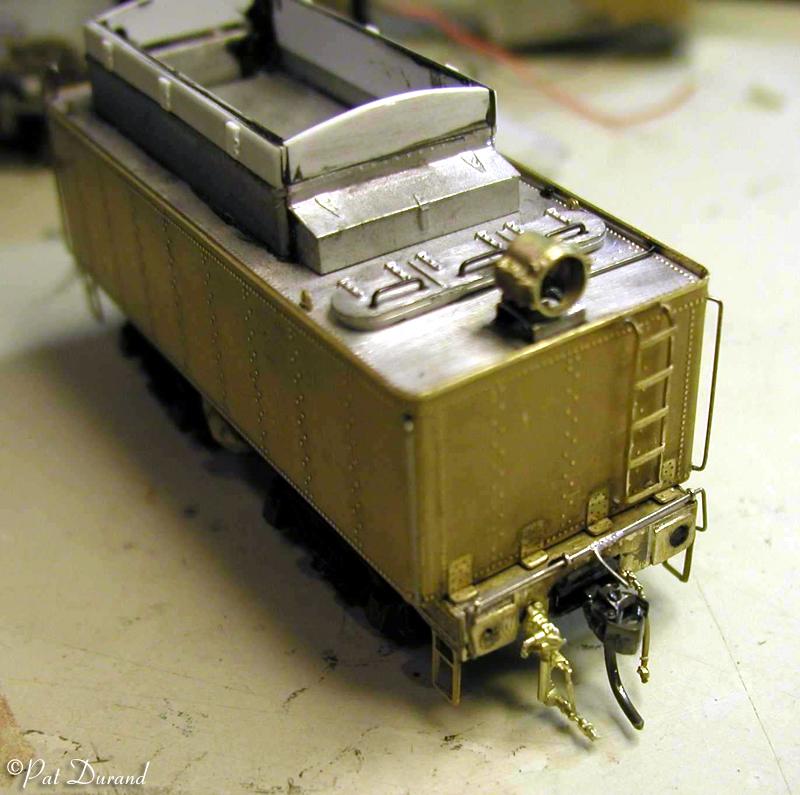
With the top tank deck assembly pressed in place, then carefully add the floor (11) and the coal front (13) fixing with Tire Glue only to the water legs and the tender floor. Now remove the top tank deck assembly. I prefer to add real coal to the bunker. Add the brass lift rings and brake wheel from the kit. Brackets for the rerail frogs, and push pole are made from brass wire and soldered to the sole bar (4) (tender frame). Poling pockets can be fabricated from brass sheet scrap and soldered to the corners of the rear
The Pyle National headlight is center mounted at the rear. I drilled a hole in the bottom of the casting and matched it with a hole through the top (7) (tank deck) to allow installation of a back up light. We will revisit the tender during installation of the DCC decoder and sound. If you are going to run straight DC then install the coupling pin (16). If DCC is intended enlarge the hole and tap it 2-56 and install a 1/2 inch 2-56 screw allowing it to bottom out against the floor (11).
All grab irons are formed from .015 spring wire, so save the brass wire for piping. Steel will hold its shape and when the paint is brushed off they will show steel instead of bright brass. All the holes are opened with a #78 drill. Grab irons are then installed with long ends extending inside the tank where they are fixed with Tire Glue placed from the tip of a pin. The long front grab irons, pose a challenge as they appear to be fixed in both the tank side at the bottom and into the tank top at the front corners. Open a notch in the corner of the tank top to clear the grab iron which is bent down and attached to the inside of the tank corner. You can solder these grabs in place if you take the time to tin the steel before inserting them into the holes.
Drawing #2 Assembly of the Tender Bogies.
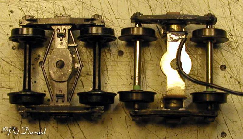
After spending three hours and doing a credible job on this step, they just looked to clunky! On review, I noticed that the Alaska Railroad tender trucks did not have leaf springs. The Kadee #509 Andrews truck at $5.75 list is the proper truck for our tenders. The photo shows the Kadee #509 on the left and the kit provided truck on the right. Notice that the wheels provided in the kit truck are closer to proto tire width than the Kadee. The overall width of the Kadee truck is more scale and it has finer detail and cross section.
Don't bother building the kit trucks. Take the nice kit insulated wheel sets and install them in the Kadee sprung truck. The result is a very smooth flexible truck. Make sure both hot wheels are installed to the right side for pickup. Mark the back of the hot wheels with a red dot for (right) and place a matching dot on the truck bolster right side and on the tender bottom right side.
Take the two boggie stretchers (34) and cut them off to form a spacer washer that will set on top of the tender truck bolster and mate with the boggie pivot (19) body bolster. Ream the truck bolster out to clear a piece of 1/8" brass tube. Cut two pieces of the brass tube 5/32" long. Remove the spring from an old ball point pen and cut off three coils. This should fit over the outside of the brass tube and ride against the bottom of the truck bolster and be held in place by bearing washer (38) and truck screw (39). After this is all fitted up take it apart and polish all the mating surfaces. You will have a very free running set of trucks with excellent electrical pickup qualities when you get it back together.
Roll that tender down the track! I hope this has been a confidence builder for you. It was for me. The next steps working with the etched sheet brass are no more difficult, just more bends.