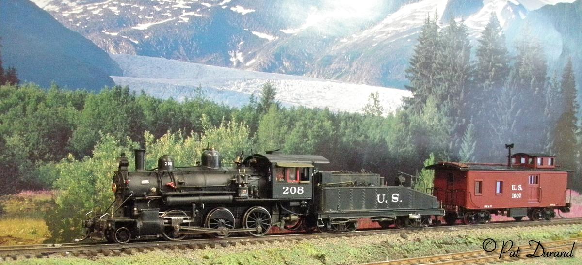
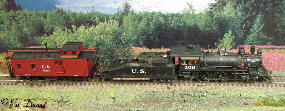
As a kit basher my goal is to capture the esence of the prototype locomotive at a given time and place. Staging the model to match the prototype in comparison tests the effectiveness of the effort. So here is the final result for #208 followed by a second hand Colorado Midland caboose as seen at the end of the prototype photo. More on the Caboose later.
Patience has been rewarded. I have been waiting for some builder to come out with a dependable model steamer that would provide the foundation for ARR class 200 Panama Moguls.
When I first saw
photos of the new Bachmann ALCO mogul, on blind faith I ordered three units
with sound at an unbelievable prerelease price. Just got them and spent the
last hour running the little critter. It is a dream, smooth and comes out
of the box with a Soundtraxx sound decoder already tuned to this locomotive
driver
revolutions. There is a limited sound set but everything you need is there.
Lots of nice detail and robust construction, not a bunch of stuff to fall off.
If you have been looking for a proper Alaska Railroad Steamer, this is the closest thing to come out of a box yet. Go for it. There are lots of 200 class prototype photos at alaskarails.org under FORMER > LOCOMOTIVES > STEAMERS.
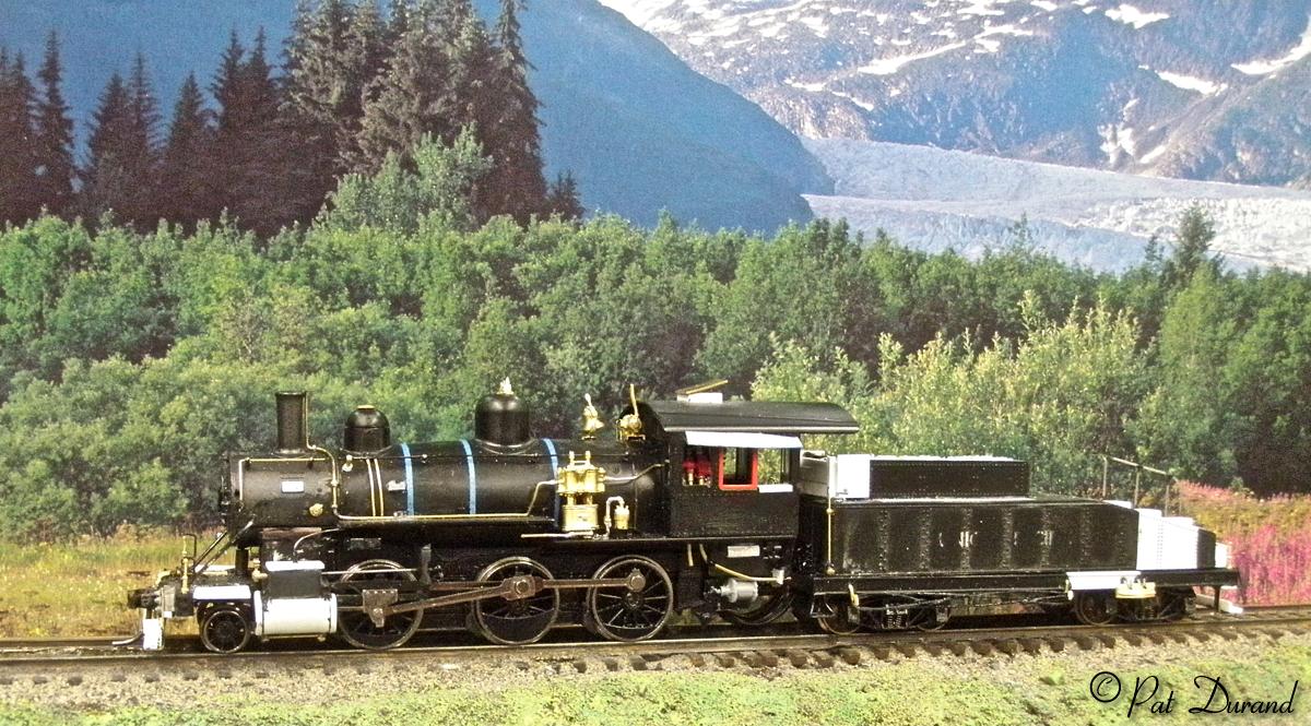
Scale measurements are all closely comparable to the prototype 200 class drawings in THE ALASKA RAILROAD by Prince including the 14' height. Overall length of the model is 2 ft short but that all will be addressed by an extended slope back tender. Driver spacing and diameter are very close. For most folks a paint job and lettering would do.
These are the changes I plan on:
Deconstructing a Panama Mogul
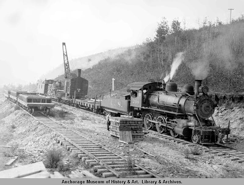
Ship Creek landing and Anchorage, Alaska in 1916 had no provision for unloading a complete locomotive. Locomotives arrived as kits to be reassembled in the Anchorage Yard. The Panama Moguls had been used during construction of the Panama Canal on the 60" or 5 foot gauge railroad. They were deconstructed in the Panama City shops for shipment to Alaska. In the process the wheel and axle sets received new wider tires that moved the flanges in 1.75 inches to arrive at standard gauge of 56.5" for Alaska.
Bachmann was good enough to provide the Alco Mogul with standard HO gauge wheel sets to begin with. None the less I have DECONSTRUCTED the mogul in preparation for the modifications to match photos of the Alaska Railroad 200 class moguls. Before you start the process decide on a prototype. Study the photos and make note of unique features on a parts list.
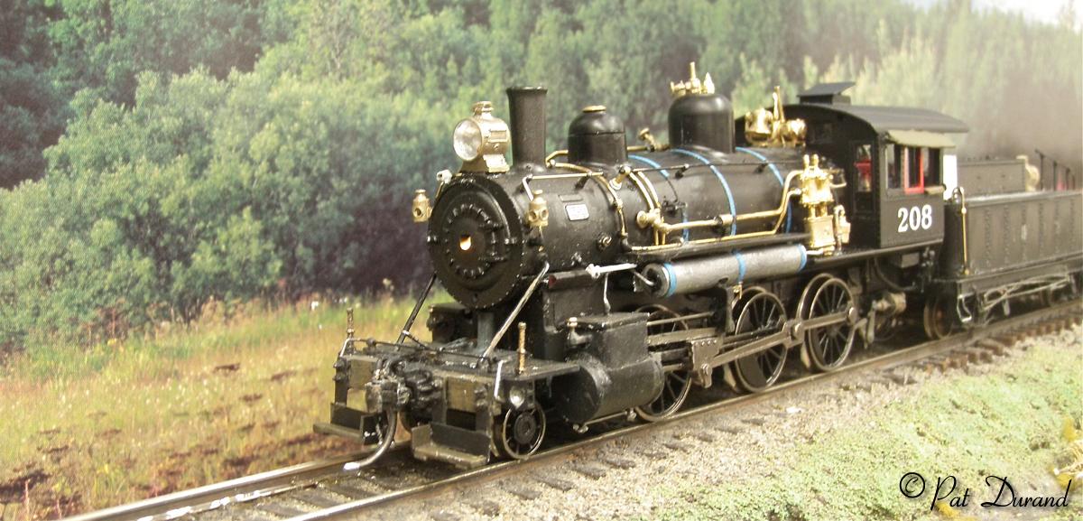
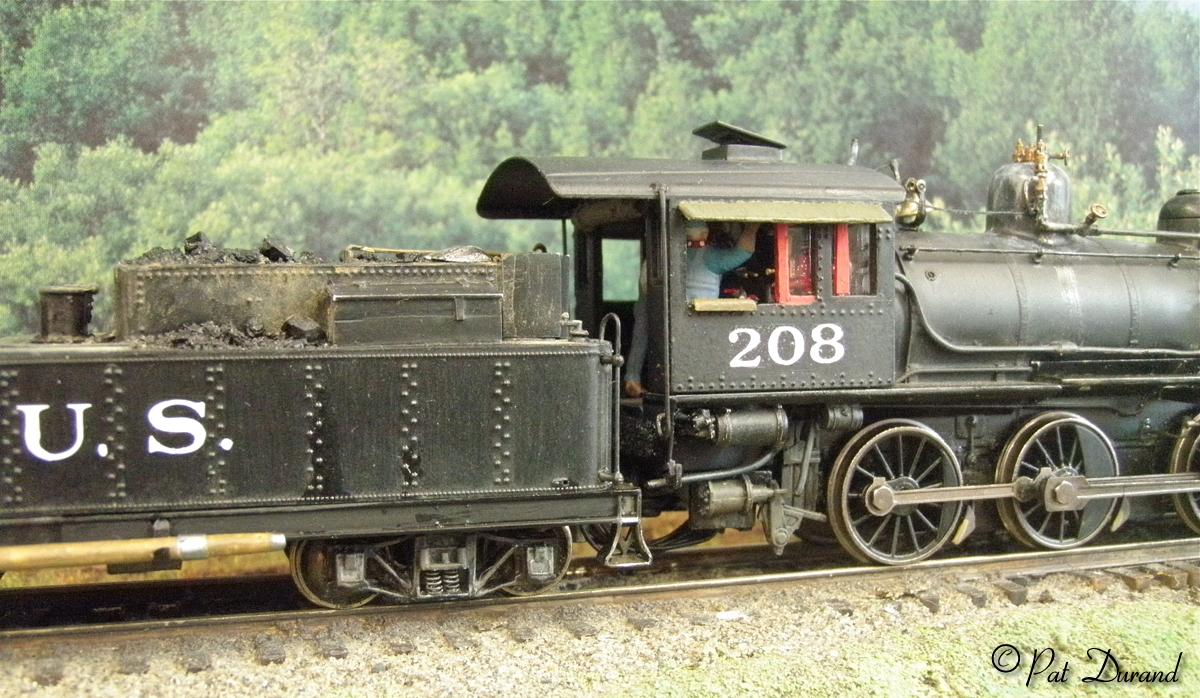
208 was one of the first to arrive and eventually go to scrap in 1930 so photos are rare and show her in the as delivered condition with the large Arc Light headlights, New York compound air pump and the steam line going forward from the steam dome to the front of the smoke box along the top of the boiler. Several of the 200's had the steam line which was connected to a large winch mounted on a flat car in front of the locomotive as part of the Lidgerwood Unloader.
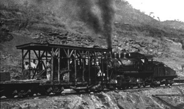
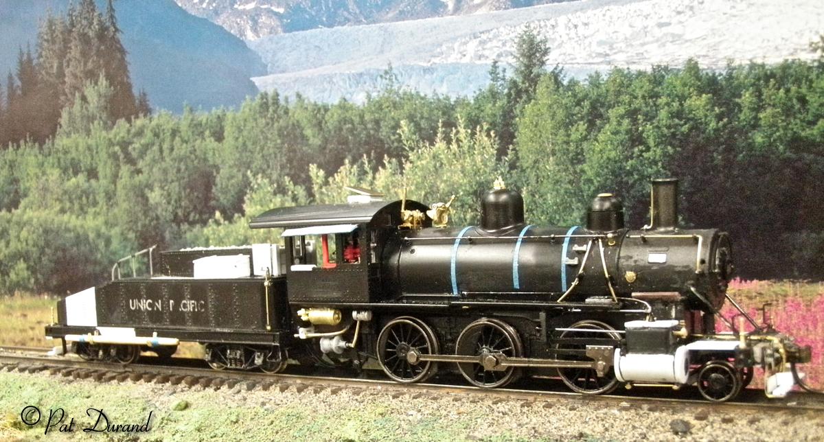
Number 208 will represent the class as used during the construction phase under AEC control and will have U.S. on the tender.
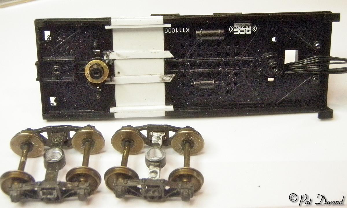
DECONSTRUCTION starts with removing the tender and setting it aside for now. CAUTION: There is no need to remove the three screws that retain the drivers and electrical pickup components.
1. To remove the cab, first disconnect the two very fine but tough wire hand rails from the chassis at the bottom. You can reach the back side of these where they are inserted into the chassis and apply a touch of unglue or cut away the adhesive there and press the wire out from the back side. Now insert a small screw driver through the opening at the back of the cab and into the daylight crack seen under the cab side, a little pry up will release the tabs and then slide the cab strait up and off the boiler.
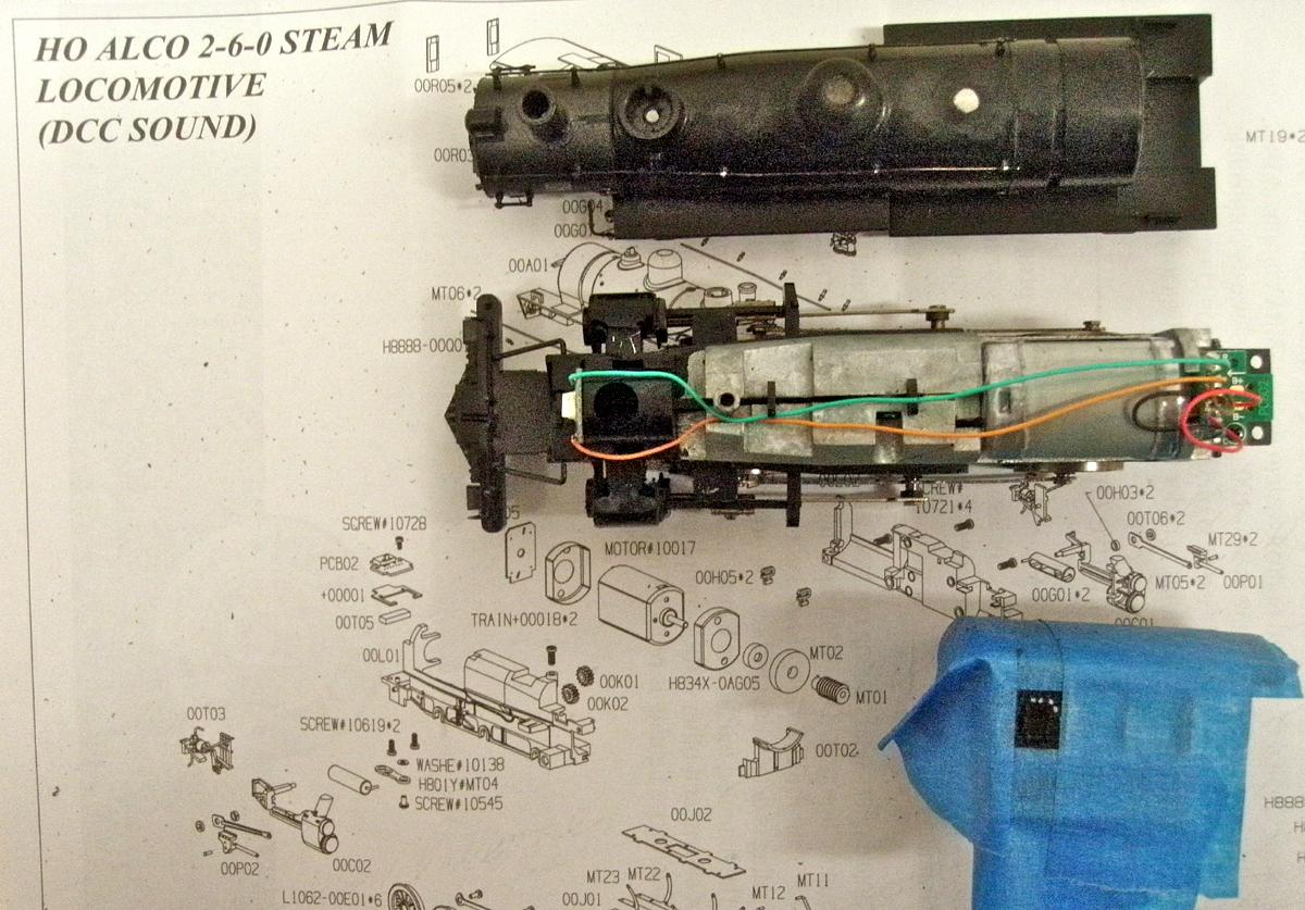
2. The exploded view does not reveal the small screw 00610 hidden under the sand dome cap. Then come the two screws 10619 at the rear of the frame inserted from the bottom. Next remove the pilot support rods from the holes at the sides of the smoke box. Now grasp the edges of the firing deck and while gripping the chassis at the rear simply rotate the boiler forward and you will have tow pieces. Very sophisticated engineering! You now have three components on the bench and three screws in your parts holder.
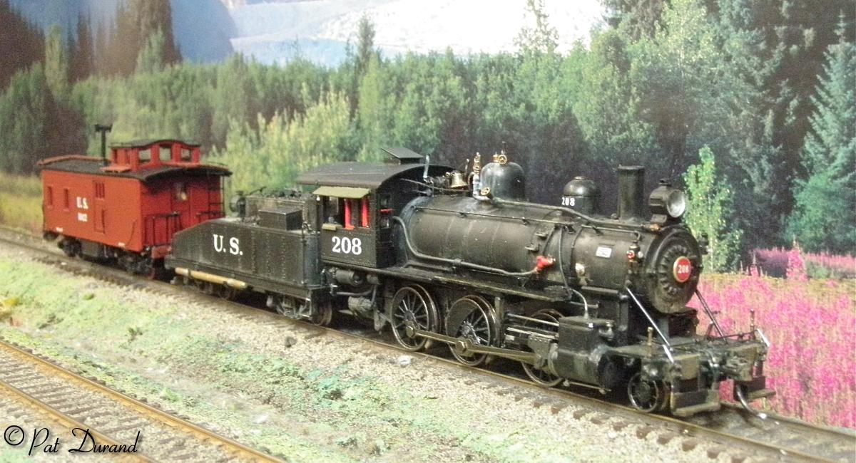
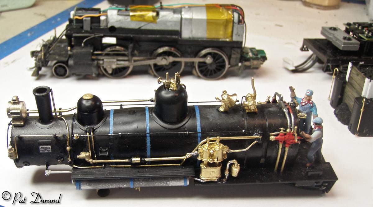
KIT BASHING DECONSTRUCTION CONTINUES; Robust describes both the construction design and the materials employed by Bachmann. The plastic used is a marvel for kit bashers, tough, resilient, excellent shape memory and yet it cuts like butter if you use sharp tools like a #11 blade. From this point forward keep referring to your prototype photos for guidance. I am building 208 as of 1916.
3. Remove the steam pipes from both sides of the smoke box. 200 class had D valves with steam passages internal to the cylinder block.
4. Remove the auxiliary steam dome where the safety valves are. 200 class had these mounted on top of the Steam dome and the bell will take the place of the auxiliary dome.
5. Remove the bell. If you plan to replace the bell and generator with brass parts remove the generator also. There will be a parts list at the end of the article.
6. Chisel off the cast on pipes from the sand dome down and the check valve with its plumbing.
7. Decide if your model will have the standard Westinghouse Cross Compound air pump or the earlier New York style and then either retain or remove the plastic pump from the boiler left side.
8. The raised portion of the right front running board should be removed from the boiler shell. Do retain the part as it will be reapplied later in a lower position. Cleanest removal is done with three swipes of a sharp #11 blade at the joint where the running board meets the boiler. After the joint is well scored you can just bend it down to break it off in one piece. Leave the left running board alone. Slip off both the right and left air tanks and retain them.
9. Saw the steam pipe off flush with the top of the cylinders on both sides.
10. 200 class moguls had Stephenson Valve Gear which is all inside the frame with only one little crank and valve rod showing externally. The Model has Walshaerts gear with the eccentric crank and rod connected to the center driver. Good news is that most of this conversion is just deconstruction. Remove the crank pin screw from the center driver. Make a wrench by filing a notch in a scrap of metal, if you don't have one already. The pins are standard right hand thread. When the valve gear eccentric is clear replace the crank pin screw.
11. Use a small pair of clippers and cut the drag link flush with the bottom of the crosshead. Then saw the portion of the bracket holding the valve gear components away from the back side of the crosshead support. See the photos below for clarification, you don't want to cut the wrong place.
12. Remove the cast on slider hatches from the cab roof. Mask off the rain gutters and those portions of the roof you want to save and use a file to smooth the surface and finish with 600 grit paper. I used the center hatch as a guide to drill down and cut out the space for a real hatch to be added later. Note how masking tape is used to define the space to be removed for the cab side window addition. I always mask areas adjacent to work zones to prevent nicks and preserve details. The masking also gives better control of the work piece.
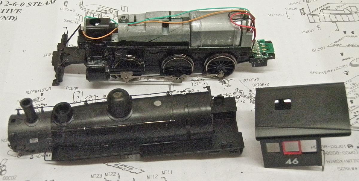
Deconstruction should be near completion and the three components should look like this:
RECONSTRUCTION of Panama Mogul #208
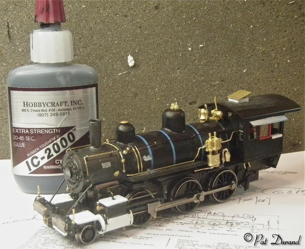
Kit bashing requires the acquired skill to recognize when good enough is good enough! The techniques employed here are at best called "mixed media" and trial and error are the instructors. None of this would be possible for me without IC 2000 or as I call it Tire Glue. It is viscous, does not migrate, does not gas off and discolor surrounding materials. It is strong and the rubber in suspension provides resistance to shock. It will glue most anything to anything and that is desired in kit bashing, You can weld up holes, fill cracks and create small details with it when used with accelerator. If you goof up, just apply a little "UnCure" to dissolve the joint. In most every instance I add a mechanical pin or metal bracket in addition to the adhesive. All brass to brass connections are soldered. Use lots of flux and very little solder.
For a discussion of adhesives and soldering techniques go here.
The locomotive weighs 6.6 ounces out of the box. #208 now weighs in at a full 8 ounces and we are not done adding brass parts yet. Still waiting on check valves, whistle, arc headlights, brake cylinders and a 10 ft long air tank that will be filled with lead. In the process of reconstruction, keep an open mind to adding lead where ever open space allows. The stack and steam dome were filled with small pieces of lead fixed with IC 2000. The firing deck well was filled with a 1/4 ounce lead weight to bring the deck up to proper level. The interior of the cab roof receive a 1/16 th inch layer of sheet lead. The body weight contains a number of voids where lead can be added but be sure you do not bridge the electrical separation of the two halves of the metal chassis particularly at the bottom of the plastic enclosure for a possible smoke unit under the stack. The void above the lead truck was filled with lead blocks to simulate the frame extension and another block of lead was added behind the axle on top of the truck frame.
I will let the following photos speak for themselves as to the parts to add or relocate. Notice the grab iron on the smoke box front originally was located below center creating a smile, and it now creates a frown overhead. The smoke box handrails have been replaced, by retaining the two short stanchions and adding a third to secure the down turned end. A new longer stanchion was added at the forward end of the boiler jacket to support the end of the hand rail after it was cut short of the smoke box.
Holding no intention of filling the boiler with water and building a fire on the grates, there is no point in hooking up all those pipes. Just make it look like they are going where they belong. OUT of Sight, Out of Mind, if you can't see it, your brain will accept your well placed clues that everything is in working order. The little details are just sugar to make the suggestions complete the image. That is one of the benefits of kit bashing a locomotive for yourself, you know the customer and you can tell him to ........ get a life. My intention is to complete a representative model in this lifetime. I already have a good inventory of unfinished projects.
Examples of mixed media, the blue bands on the boiler jacket are made from masking tape as are the cab window awnings. The rolled up canvas weather curtains are the same material. These are put in place and then infused with Instant Cure super thin ACC which wicks under the tape and fixes the adhesive for ever. The tape becomes another piece of plastic with fabric reinforcement. The top of the steam dome was drilled out to make a home for the safety valves. Round lead sinker weights were flattened in the vise and then dropped into the dome from the bottom to create the flat top of the steam dome below the jacket. The dome was then filled with lead held in place with tire glue. The round balls on the ends of the hand rails are successive drops of Tire Glue left to cure. The oiler fittings on the line going into the top of the steam chest are a build up of Tire Glue. The cylinder cocks are small brass nails with the heads smashed and filed to shape.
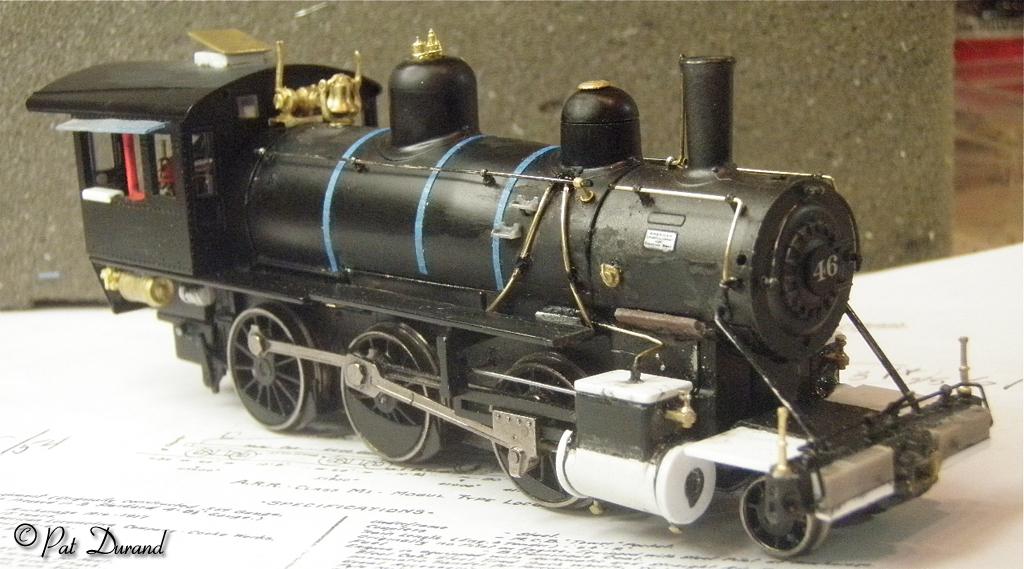
The right side running board has been reattached in the proper location. The cast on trunion that held the air tank has been ground down to less than half of its thickness to provide support for one end of the shortened running board. A flat brass strap on the opposite end provides support. The new Stephensen valve rod has been installed and you can see the modified cylinder chest. The end caps were cut from .040 styrene using a leather punch held in my drill press to apply the force. Only the ones on the front are complete circles. At the rear of the cylinder they have 1/3 of the circle pie cut, to clear the piston and crosshead guide. Prior to all the white styrene being added the old cylinder block was squared off using a zona saw and files. The new cylinder outline was created with .020 styrene sheet.
The pilot beam has been modified with the new extended flag holders. The old tube pilot was removed and styrene spacers installed to simulate the wood spacers used on the prototype to move the foot steps forward, gaining clearance for the ice flangers normally mounted on the front pilot during the winter. The flanger was important on the Panama Mogul because the extra wide tires used to convert their wheel gauge would bang on the ice left at every grade crossing. The scale size KD coupler has been modified to mount through the brass casting for the drawbar and will be held in place by a pin dropped through from the top of the bolster. With the short wheel base the coupler needs very little lateral motion to still be functional.
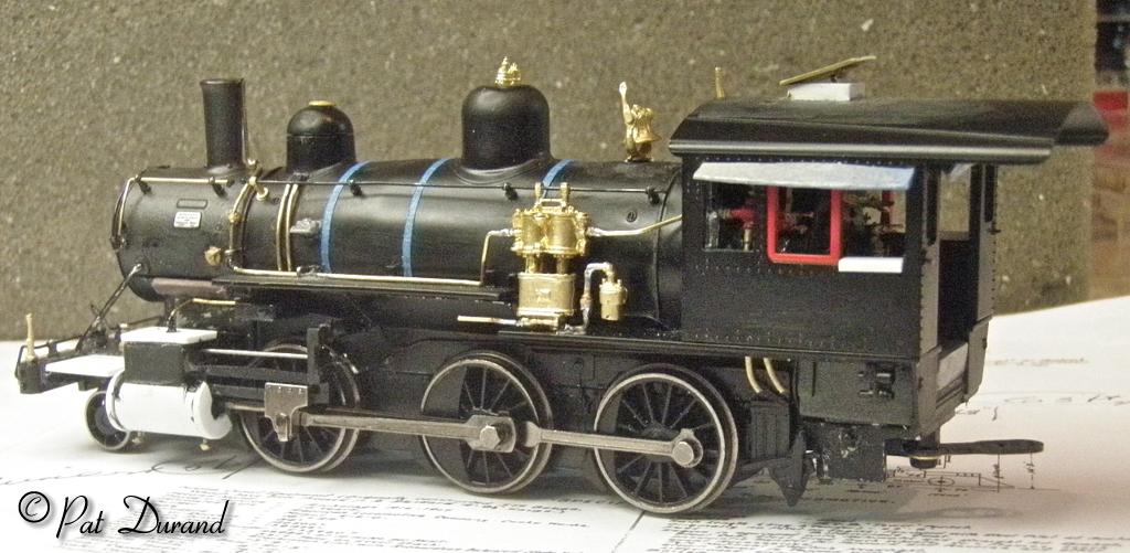
Brake cylinders and extensions of the water and drain lines for the injector will fill the void under the cab. All the cab detailing was added because of the greenhouse nature of all the windows. In the final finish glazing will receive red trim as will appliances like the check valves, and injectors. Some of the plumbing connections will be polished brass to highlight them. If not highlighted there would be little purpose in adding those details.
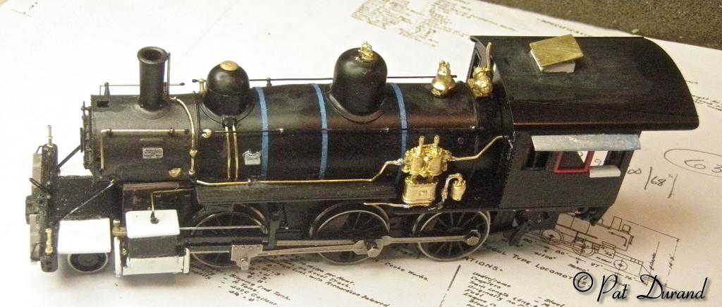
The boiler tube pilot has been removed and foot boards will be installed. Note these photos are magnified several times larger than the actual model. These are studied to determine where final cleanup and touch up are required before the commitment is made to painting the model. This is where your judgment as to what is good enough takes over.
Next comes the slope back tender while we wait for parts.
Kit bashing the Panama Tender for ARR #208
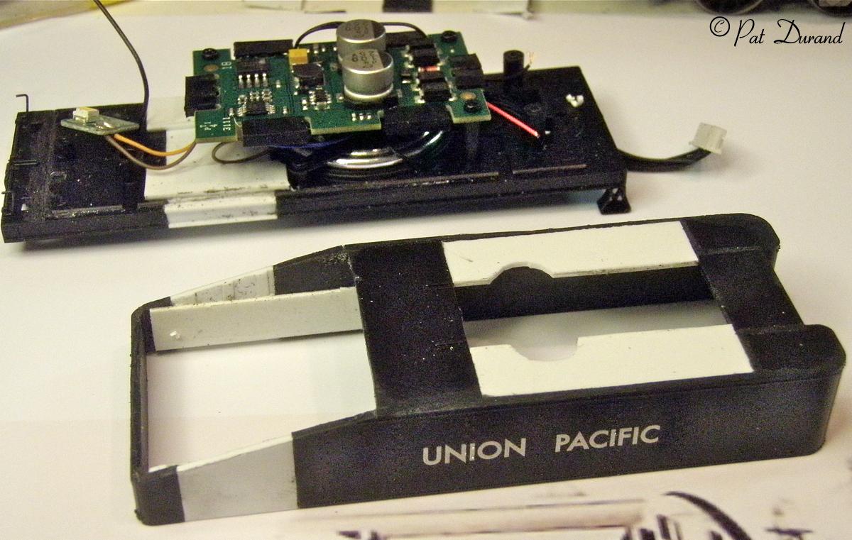
The slope back tender for the Panama Mogul, was a bit intimidating because it had to contain the sound decoder and electrical pickup. I got out the proportional dividers and studied all the photos available and established some basic measurements. Suddenly it became a simple chop and glue kit bash of the Bachmann tender.
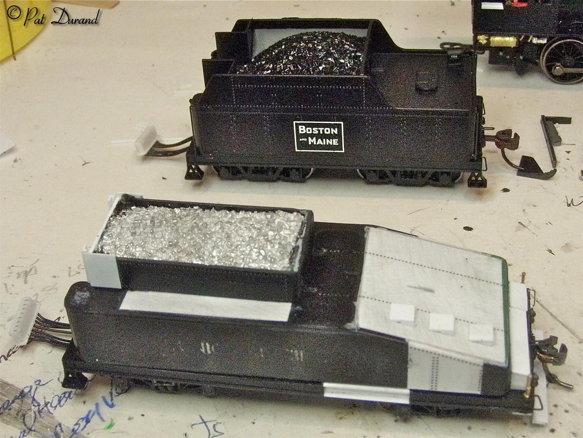
The arch bar trucks of the prototype have a 64 inch wheel base, so that became my base number and using the proportional dividers i roughed out the measurements for the tender. I'll save you the trouble of all that.
Length of frame, end sill to end sill is 27' 8" so it needs to be stretched 58" to allow for the tool box on the rear sill behind the tank. After removing the decoder and original trucks, cut strait across the frame just forward of the rear bolster. Use .040 styrene to fill the void and add sandwich pieces on both the top and bottom to secure the joint. This is all styrene so I used MEK to weld it all together.
Trucks are Kadee #501 archbar with electrical pickup added to the insulated wheel side to arrive at all wheel pickup. The center bowl of the truck will need to be drilled out to fit the body bolster pin. This will take some fit up to get electrical connections and keep the tender at it's original height.
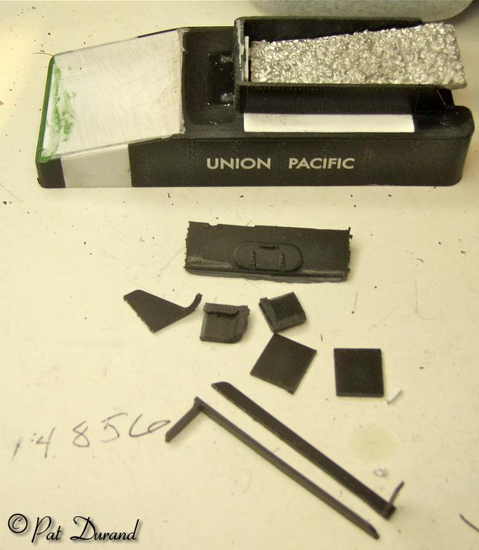
The tank is 25' 8" long when finished with a 48" filler splice in the sloped sides. The tank height comes out at 50" which amazingly is just the height of the water legs on the Bachmann tender. So the first cut is to use a new zona saw and remove the coal bunker and tender sides flush with the top of the tender deck. Easy does it, try to keep just above the horizontal rivet line to give you a nice guide and finished surface. The prototype tanks are flush on top with nothing to capture trash.
The second cut is a vertical slice removing the last 21 inches of the tank and saving it aside.
The third cut removes a portion of the tank top. Measure back 16' from the coal retaining boards at the front of the bunker and make a line across the tank top. From that line back you will be removing about 34" of the tank top while leaving the side sheets in place.
Next cut down the remaining portion of the rear wall of the tank until you have a section 28" high from the bottom up. Imagine the black pieces in the photo without the white styrene in place. Styrene filler pieces about 48" wide give or take for the accuracy of your cut are now installed in the tank sides. When this assembly cures fit it to your extended frame.
Now measure from the rear deck up the back of the tank sheet 26" and mark that measurement at the rear of each side sheet. An angled line drawn from that point to the new back edge of the tank top should be 8' 8", mark it and that will be the slope angle on the tank side.
Now you just need to add .020 or .040 styrene to create the new tank top filler pieces. Note the cut outs needed under the coal bunker to fit around the components on the decoder board.
Do the finish sanding and cleanup and give the tank a light coat of clear gloss. This is the foundation for the decal rivets (you can get them from Micro Mark). After the decals cure you give them another shot of clear gloss and they are part of the tank.
Now take the remains of the side sheet and the top section of the rear tank sheet that you had cut away earlier. These become the sides of the new coal bunker. Without closing this hole in the tender tank you will get no sound out of the speaker. Some photos show timber side board extensions and others have head breakers over the front of the coal bunker. When you have finished the three sub assemblies for the slope back tender, there is very little left of the original.
After the tool box at the rear deck is glued to the tank, drill and tap the coupler screw hole for 2-56 and run the tap right up into the tool box. Now secure the tank at the rear with the coupler screw and at the front with the original small screw.
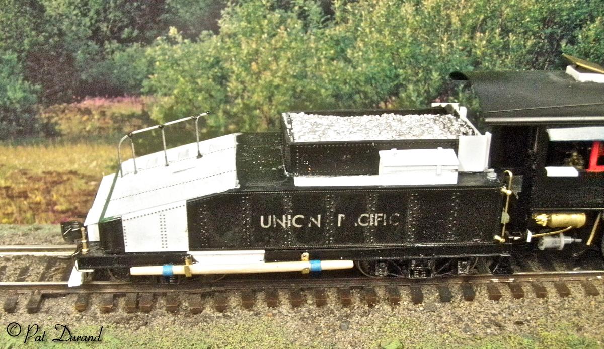
From the prototype photos, duplicate the steps, grab irons, hand rails, poling pole with brakets, rerailer and the ever present wire rope. When crews were working on stub tracks with the side dump cars and flats, it was common to use the pole and or the wire rope to push or tow the cars to a location where couplers could meet. Still waiting for the Arc Lights, poling pockets and the high water hatch details to arrive. Lots of brain drain here but it is all worth the effort when you see it in final paint.
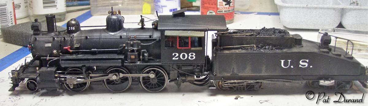
U.S. 208 Getting er done!
The final shipment of parts from Precision Scale arrived and within hours #208 was ready for the paint shop.
Parts list for Mogul U.S. 208 cir 1916 on Alaska Railroad
Precision Scale Company
Cal Scale Co.
Kadee #501Arch Bar trucks
North West Shortline 37217 33" Wheel set for tender pickup
Cary 13226 Valves and Pipes
Various size brass and steel wire for plumbing and hand rails.
Various grab irons.
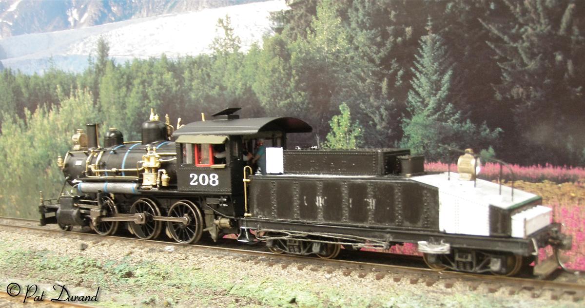
The cab was removed and then the boiler shell to reduce the structure to three components. The chassis was hand painted so it was not necessary to tear it all down. In similar manner the tender body was removed from the frame. The boiler assembly was masked to protect the builders plate, head light lens, bell and the cab interior with the crew. Coal bunker and back up light lens were masked on the tender body.
Take notice of the unpainted airtank under the left running board. This is a solid cylinder of fishing sinker lead cut to length for this 16" air tank. The bands are blue masking tape. With this additon the weight on drivers is now 8.6 ounces up a full two ounces from the stock 6.6. This should translate into a 30% increase in tractive effort.
Both boiler and tender body were airbrushed with PolyS Locomotive Black. The paint was only allowed to cure about 4 hours and then the weathering, wear and highlighting was done while the base coat was still soft and had some bite to hold the pigments from the various techniques. If you think the weathering is overdone, realize you are seeing the finished product several times life size and under extra lighting.
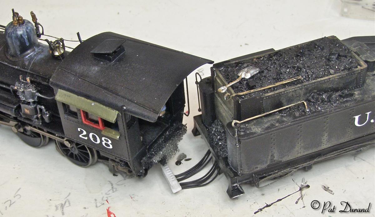
It was obvious a void between the tender and cab
needed to be filled where the gangway and buffer should be located. Any rigid
structure there would result in inhibited performance. Something needed to fill
the visual void and a small piece of soft foam was cut to the outline of the
missing deck and buffer and then glued below the firing deck of the loco. When
the tender is connected you have to believe all is in order and Renfreu, the
fireman, is not going to fall to his demise
between the loco and tender.
Notice the hand rail extending from the cab roof to the rear cradle is the only solid connection between the cab and the frame. You may want to leave the bottom of the hand rail loose to make the cab removal possible. The cab and the boiler can be removed as an assembly.
In my experience the most common problem encountered with model steam locomotives today is failure of the multi pin electrical connections between locomotive and tender. These plugs are not designed for repeated connection and disconnection which is required if you put the locomotive away in its original factory packaging. So avoid the hurt and grief. Visit your local sports collectors shop and pick up some 12, 14 and 16 inch long baseball card boxes. Usually a $1.50 but ask for them knocked down (unfolded) for $1.00 each.
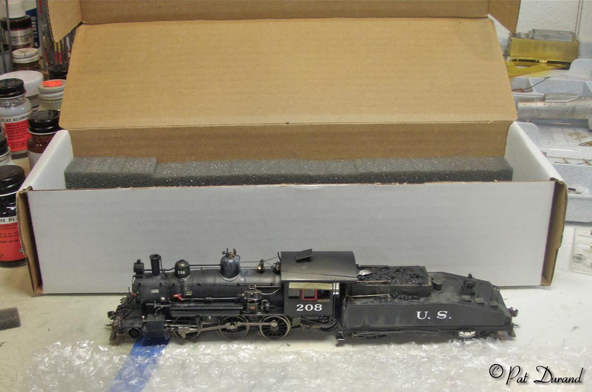
Get some 1 inch thick foam and cut it in two inch
wide strips. Use double sided tape to attach the foam on the two long intterior
sides of the box. Cut a square of bubble wrap to make a sling for the locomotive
and tender leaving them connected. Drop the locomotive in its sling into the
box between the foam and fold over the exta bubble wrap. Close the box and give
it the drop test if you dare. You can add the history of your locomotive along
with your build date, decoder
info etc inside the lid.
Have some fun with your camera and see if you can get close enough to identify the crew. Here William (another Wild Bill) A. Smith, engineer and fireman Renfreu, are struggling to make steam with the bony sulfur laden coal from the temporary tipple at Houston. There is no crusher there so they just get it in "chunky" form.
The 208 has been performing well and is a great puller with added weight. I plan to build up two more of these little gems to represent various modifications during their service life on the Alaska Railroad. Hope we can meet along the tracks.
Pat Durand