I am up to about 36 hours now on the Nenana Depot and if I had just followed the instructions it could have been done by now. I figure I am about half way to meeting my goals on this project and then another 10 hours or so detailing the inside.
Goals:
I have been doing more research on the building and
I'll keep records and share details for those who are interested.
In no particular order these are some of the discoveries I've made and
solutions to modeling the Nenana Station.
Special Tools: Lots of single edge razor blades and #11 blades. You need sharp tools. The self adhesive materials are fantastic but you need tools that make a clean cut so as not to displace the adhesive. Needle Nose Tweezers are the best tool for separating parts from the adhesive backing sheet. Gap filling Super Glue works great on the wood if you soak any end grain first and then reapply to make the joint. Keep several old model boxes handy to separate and organize parts as they come of the stock sheets. There will be stock sheet materials left over to build several out buildings.
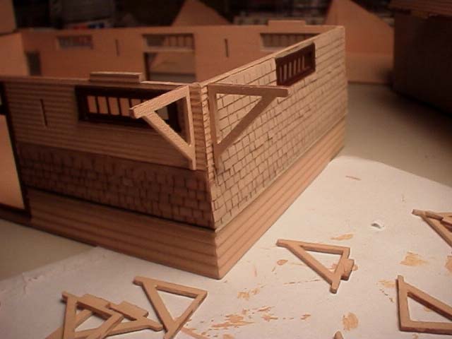
Corbel supports for the roof soffits: The Corbel supports are nicely made but very dainty. I broke the first four I applied by bumping them later when I tried to attach shingles. Solution: Soak these little critters in gap filling ACC applied to the end grain of the wood and set them aside to cure overnight. To finish drag them lightly over 300 grit paper and then paint all but the attaching edge with two coats of your finish paint and dry overnight. Now they are tough. Do not attach these until the last step. If you are applying shingles up the side of the building, you can go up five courses all around before you need to attach the corbels. This step saves a lot of handling and potential damage. There will be 12 courses of shingles on the finished wall.
Shingles and Shakes: The wood simulated shingles are fantastic and are appropriate for the side walls covered by shakes. More on the roof shingles when we get to that job.
Double Hung Window Glazing: The double hung windows are fantastic. One improvement is to cut the supplied glazing into two pieces so the finished top and bottom sash are in two separate planes rather than just one. Apply the first glazing to the back of the top (outer) window sash. Then attach the bottom (rear) sash to the exposed adhesive on the back of the outer sash. The second piece of glazing now goes onto the rear bottom sash section. This makes a dainty sandwich which can then be pressed into the window opening. After applying the outside casement/trim then gently press the window sandwich from the backside, so it adheres evenly with the casement/trim. After everything is positioned, use a paint brush and apply diluted white glue in the seam around the window from the back side. A great window system now looks even better and they can be "opened". Alcohol applied sparingly with a soft paint brush will remove any finger prints you leave on the windows. Here is a photo of the operator's bay.
Parts Identification: Parts identification depends entirely on your abilities in spatial relationships. Only remove parts from the stock sheets as needed. They can be painted quite well right on the sheet. Dry fit subassembly parts before gluing them to avoid the problem I had on the short walls of the bathroom and operators bay window. The siding below the window line on the two sides of the building is aligned different. If you mix up the four little pieces that are the same size you will end up with mismatched edges on the siding. I learned. I am going to cover up these little goofs by setting a trash can in front of them.
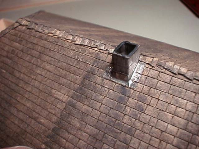
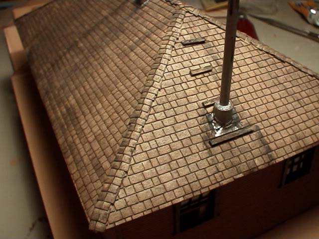
Chimneys and smoke jack: The prototype did not use brick chimneys. (bricks were not common in Alaskan construction) The two chimneys were formed up in dimensional lumber and poured with steel reinforced concrete. The one in the residence roof was rectangular and comes up to the north side of the roof ridge. This chimney served the cook stove upstairs. The main furnace chimney is 24 inches square and originally served a coal fired furnace. These can be modeled very well with Plastruc square and rectangular tube, scribed with mortar lines, sanded and painted. The aluminum smoke jack and chimney on the West end of the residence served a replacement oil fired boiler. This is modeled with successive sizes of Plastruc tube, scribed for the joints and painted. Note this feature changed over the years from the early galvanized stove pipe to the later "Metal Best" insulated style.
Interior items will be attached to a sub floor about .04 thick to bring the interior floor up to the door sills. When I have determined how the roof will separate, I'll proceed with the ground floor detail. The residence floor plan was provided by Randy Thompson, so that section will be detailed first with fixed interior walls attached to the drop in floor panel.
On a model of this size the first question is, "Where to start?". I suggest you build the second floor residence to learn how to use the materials and techniques required to complete the rest of this excellent model.