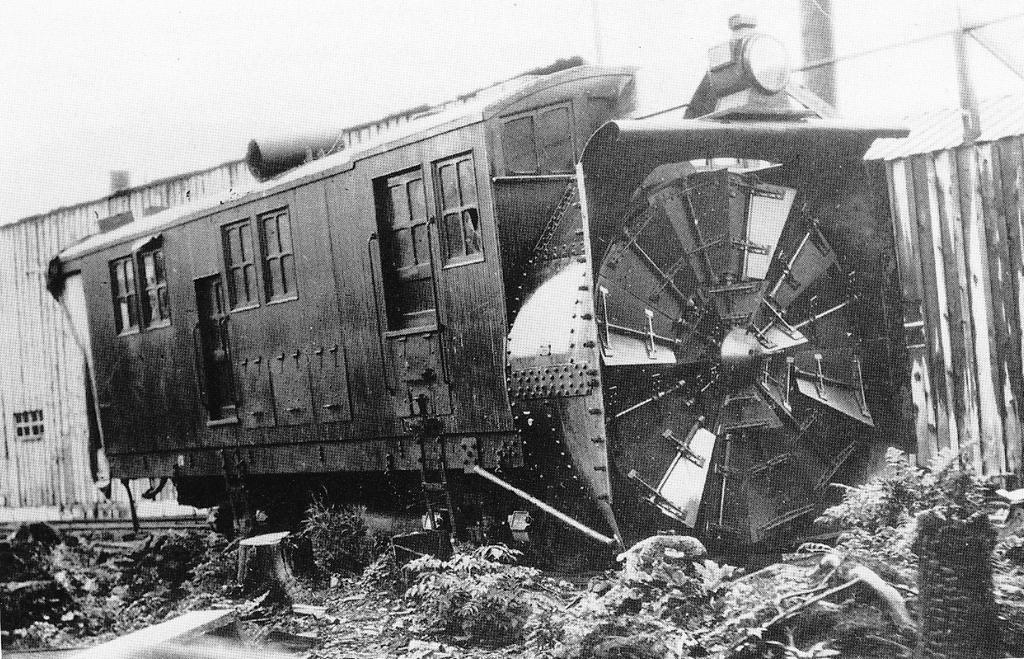
The first Rotary snow plow used on the Alaska Railroad was Rotary #1. There are two viable photos, fortunately one of each side of this machine. The earliest is undated but appears to be of the Rotary on its arrival as used equipment on the Alaska Central Railroad in Seward. The lack of a tender and the old headlight indicate this was on arrival and before transfer to the Alaska Northern in 1906.
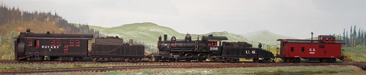
The second photo is not dated, however it was taken between 1918 and 1923 when the AEC (Alaska Engineering Commission) turned over the roster to THE ALASKA RAILROAD. AEC equipment was all labeled U.S. until the transfer in 1923. The rotary is being pushed by a 600 class mogul and a 200 class mogul and followed by two cabooses, the first one being an old Colorado Midland caboose. Click here to view the photo.
Fortunately we also have the clearance drawing from the Alaska Railroad with dimensions and some history.
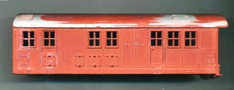
Building the model started with an old "diesel powered" rotary that represented a converted American built Rotary. Cast into the frame of the HO model was "POCHER TORINO ITALY". I have no Idea how many years this has been in my junk box. The rotary blades were powered, sort of, by a friction wheel off the front truck. I replaced both trucks with Fox Patent trucks with steel wheels and discarded the drive system. The rotary housing is a separate casting and was easily moved up on the body by a scale foot and the body lowered on the frame by the same amount. The car body and the frame were shortened by about four feet to match the clearance drawing dimensions for the wheel base of the prototype. On the body this was done by first removing and saving the rear side doors. The rear cut was continued across the roof to the other side. The finished length at the roof is 32'6". All the cast on grab irons were removed during this process and later replaced with formed wire.
To lower the doors to the proper position, a matching notch was removed from the sides of the forward section so that it provided the matching header over the door. This cut also determines the second matching cut across the roof. These rear doors on the prototype are hinged to open next to the boiler just forward of the firebox. The forward doors slide toward the rear in tracks and are about 8 inches wider than the rear doors. That is why I modeled them as open or partly open and made the expansion by removing material forward of the doors. They open onto a wooden deck where the operators controls and seats are just forward of the smoke box. The deck is elevated over the machinery deck where a set of bevel gears on the end of the rotary shaft get power from a shaft connected to quartered crank pins at each side powered by the main rods of the two cylinder steam engine. The two forward facing cylinders are mounted backwards under the smoke box and stack. All those access doors down the side are to allow servicing of the rods, crossheads and the gear drive. You will need to add an ash pan at the rear along with a draw bar for the tender.
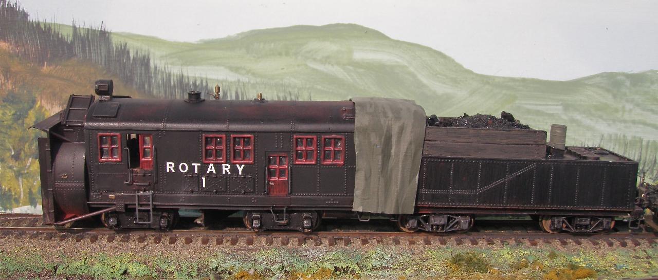
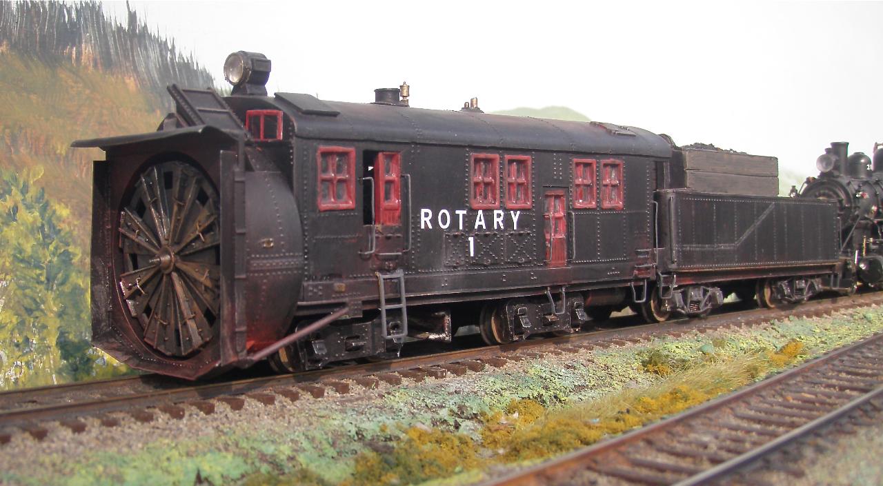
A crude boiler was built from plastic tubes and an old plastic smoke box front and then attached to the frame. You cannot see much of it on the model but it fills the void and dictates where the new stack and steam dome penetrate the roof. The original roof details were removed but for the rear hatches. New escape hatches were made for the forward roof at each side with hinges and latches indicated on the inside with rivet lines. Decal raised rivets were applied to the roof and appliances like the braces for the plow. Window mullions were thinned by filing and two angular window openings were cut in the front just below the roof line. The front surface mounted windows were cut from clear plastic with the frames scribed and painted red along with all the doors and window trim. Cutting edges and the top deflector were made from styrene and added. The Rotary Wheel is modeled in the neutral travel position and some wire has been added to simulate some of the operator bars.
The prototype tender was a hand me down from Mogul #618. The tender body is 25' 8" long with an overall length at the frame of 28'. The tender body was in my junk drawer as a left over from building my model of #601 which had a larger tender later in life. This was an AHM model tender and was close to the image in the photo after I extended the coal bunker with 3"X18" rough sawn planks. The headache bar over the front of the coal bunker is styrene and on the prototype supported a canvas drape that extended from the rotary roof out over the coal load to keep snow out. A new frame was made so I could position the bolsters correctly to match the clearance drawing specs and while doing so lower the tank on the frame. Arch bar trucks with proper wheel base were then added. All the cast grab irons were removed and replaced with wire. The tank was too wide by at least 6 inches so I cut both sides off flush with the inside of the casting, removed about a 64th of an inch from each side with sand paper on a surface plate and then glued the sides back on. The tank is now 9'6" wide. No lettering appears on the tender in photos. No backup light was used on the tender as there was always a locomotive in that position. The rivets on the tender side are decal strips.
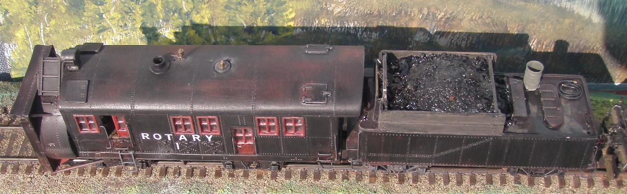
I chose to paint the rotary in a weathered black condition. Windows and doors were painted with thinned red enamel paint which left them with a weathered appearance after a finish of dulcoat. At first glance the large block lettering ROTARY 1, appeared out of place for the time frame, but it is a close match to the prototype photo. All the canvas is made from blue painters masking tape, draped over a form with smaller strips attached with the two adhesive sides mating. Once the shape is fixed, the sandwich is removed from the form and infused with super thin super glue which cures in the masking tape adhesive, effectively forming a piece of plastic. This drape is only put in place when the rotary is parked.