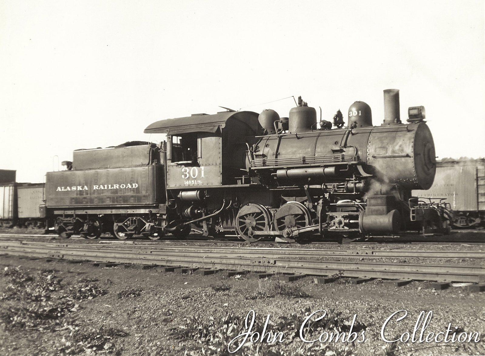
Alaska Railroad No. 301
History and Model Construction by Patrick Durand
The Alaska Railroad #301 was
the dedicated Anchorage Yard Switcher from 1943
until 1946. According to William Stewart's trip
reports, in February and March of 1946 he worked this locomotive nearly
every day and then abruptly on April 13, 1946 came the last entry for #301,
indicating her retirement was close.
She was purchased as a hand me down Class L9 from The Northern Pacific. Alco
Manchester turned out this 0-6-0 as builders #39530 in May of 1906 to became
NP No. 1042. She arrived in February 1943 to become #301 on the Alaska Railroad.
As one of a kind on the railroad, she worked the Anchorage Yard and eventually
went to scrap in 1947.
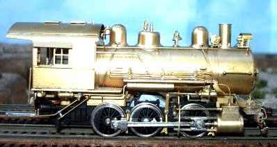
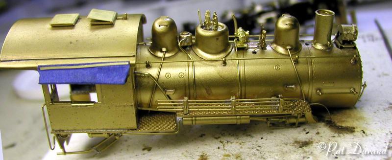
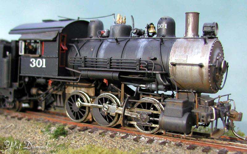
The most common brass model available from Fugiama requires some changes both small and large to create #301 just prior to her retirement to the scrap line.
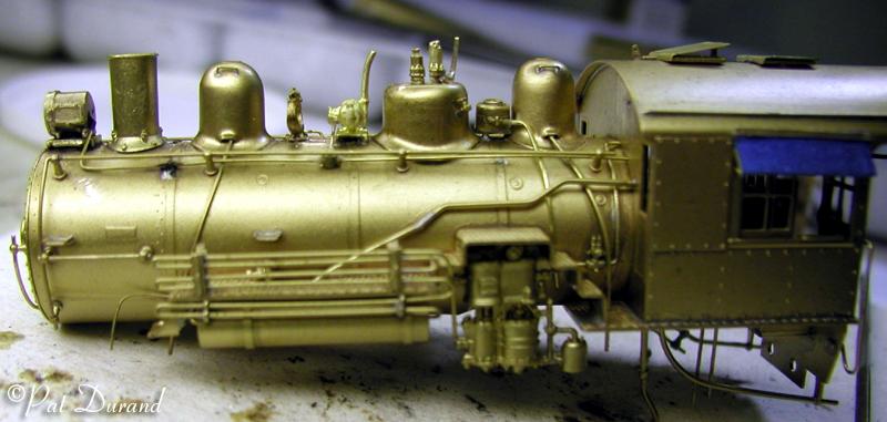
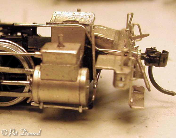
Move the bell behind the first sand dome while making room for the Pyle generator in front of the steam dome. Plumb the steam line to the generator and bring the air line out from under the jacket to the bell air ringer.
Install a replacement Pyle headlight and bracket. Drill the headlight out through the base for a lamp installation. Realign the electrical conduit from the headlight to the generator and back to the cab.
Remove the Blowdown Muffler from the front of the cab and place it on stand off wire brackets between the steam dome and rear sand dome. Plumb the incoming blow down line out and down from the muffler through the right running board as if it were coming from the single blow down valve located just above the front mud ring between the frames. A gate valve is installed in this line just below the muffler, for no apparent reason. The Muffler condensate drain line goes down through the running board on the left side. These mufflers were used on passenger locomotives and switchers operated in close quarters to platforms and adjacent tracks. When the blowdown valve was opened the water discharge was routed to the muffler where it was separated by centrifugal motion into free steam and the condensate drained off to the left side. Free steam at atmospheric pressure came out at the top of the muffler without threat to equipment or people standing at trackside. The piping to the muffler had sweeping bends and entered the cyclone at an easy angle.
A flat bar reach rod for the blow down valve should be added on the right side. Drill a hole just below the cab door alongside the boiler and extend the rod through the hole and out of sight under the step up on the running board. I make this flat bar by hammering a piece of brass wire.
The water injector line from the cab to the right side check valve should also be rerouted under the running board to match the prototype photos. Use .010 brass sheet to make hatch covers for the roof. These can be used to simulate the open hatch in the photos and the original hatch properly simulates the combing extending through the roof.
On the bottom of the cylinder block, drill out the locations for the cylinder cocks. The cocks and the operator rod are fashioned from hammered brass rod and soldered as an assembly before they are fixed in the drilled holes with Black rubber ACC. A reach rod is hidden under the right running board extending from the cab forward to a long vertical bell crank arm seen just forward of the cylinder saddle, inboard of the cylinders. The bottom of that crank rotates a cross rod that in turn has a crank arm on each end connected to the ramp that opens and closes the cylinder cocks. Add it if you must.
The canvas awnings were simulated with masking tape and the rough batten strips simulated with .010 brass strips. These awnings are soaked with thin quick setting ACC after they are formed to shape. The awning on the right side was extended to match the photos. The sliding cab window on the right side was also removed to match the open cab of the photograph and an additional overstuffed arm rest inserted.
The whistle valve lever is connected by a reach rod to a bell crank extending through the roof of the cab. The bell cord will pass through the hole left in the front cab wall after removal of the muffler plumbing.
Parts used for this modification are:
Cary Valve #13-226
| Precision Scale: | 48267 | drain valves |
| 3100 | Modern Whistle with modified valve handle | |
| 31203 | Sunbeam MO-6 generator | |
| Cal Scale: | HB 246 | Headlight bracket |
| 190-202 | Headlight Sunbeam |
Kaydee #58 couplers
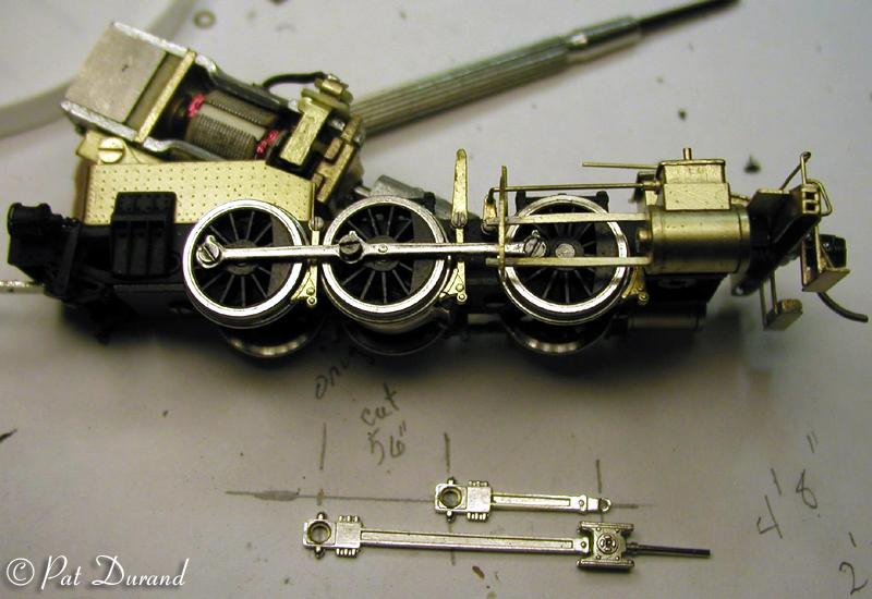
#301 had short main rods connected on the center driver. The Fugiama brass model
has the same size counter weights on all the drivers. Crank pin screws are all
the same thread size so they can be swapped around. All these feature make the
job of changing to the short side rod very straight forward. You just need to
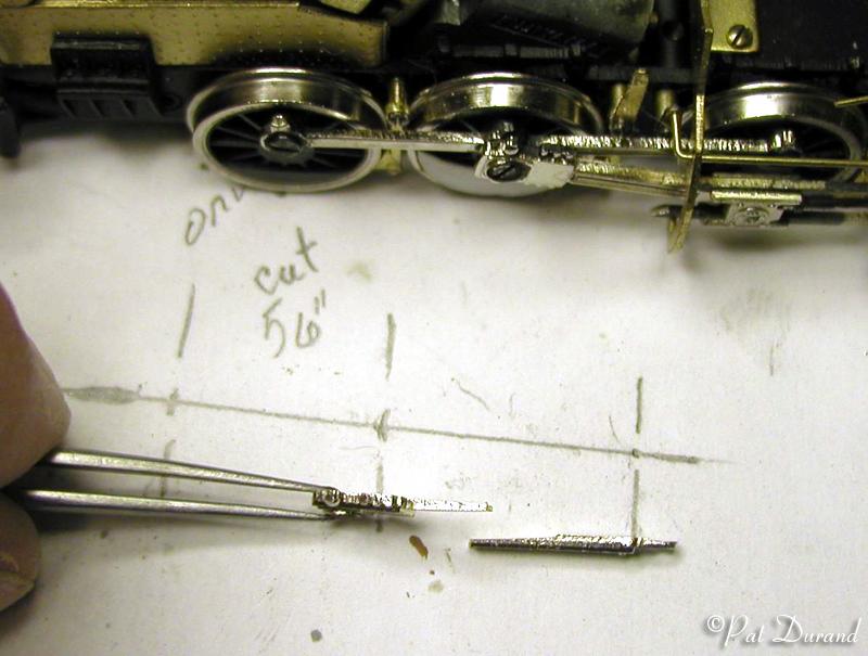
shorten the Main rod by 56 inches, the distance between the middle and rear
driver centers. This is done by making a crude drawing
of the original and shortened rods to reflect the new and old hole center lines.
Remove the rods and screws making sure you do not loose the washer that resides between the main rod and side rods. Unscrew the crosshead guide from the small end of the main rod. set all the parts aside.
Note the center and front holes in the side rods are counter bored to accept the crank screw head. Find a drill that matches the counter bore size and modify the rear hole in the side rod to match the other two holes. I do this slow and easy with a hand held drill chuck.
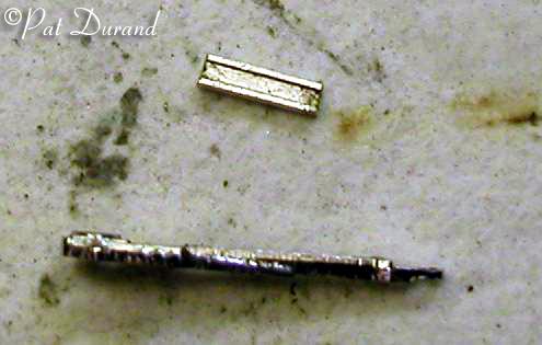
On the main rod, measure from the base of the fluted part of the rod out 26 scale inches and cut the rod off. See the attached photo to see how the taper is filed on the 26" stub that is still attached to the crank pin end of the main rod. Now lay up the two parts on your drawing and match the holes up to achieve the proper total length center to center and note how much of the mid section of the rod should be removed. Now file a matching taper on the back side of the fluted part of the rod. When a match can be made with the proper length, flux and tin both mating surfaces. Pin the two mated parts down to a soft wood board or soldering pad and apply heat to join the joint. Very little file work will dress the shortened main rod.
While you have the rods all down, take a few minutes to polish all the mating running surfaces with a very fine Emory board. From a piece of .010 styrene sheet cut a pair of counterweights to go on the center driver opposite the crank pin. Use a compass with steel points to scribe a circle with the arc of the original counterweight. While consulting photos cut the moon shaped counterweight to proper size. These are best applied with Black rubber ACC.
The ends of the crosshead guides that extend beyond the crosshead bracket need to be tapered on the ends to clear the main rod as it follows the crank pin through its travel. You may also want to secure the ends of the crosshead guides to the bracket with small applications of the Black rubber ACC on the outside contact points. These joints can be built into a fillet simulating the bolted brackets found at this location on the prototype.
Assemble the rods on the drivers, placing the small washer between the driver face and the side rod on the center driver, not between the side rods and the main rod. This will ensure clearance for the new counterweights. Check for interference by rolling the motor over by hand. Lubricate all mating surfaces and set it up for a 30 minute break-in both forward and in reverse. If any of the crank pin screws backed out during test you need to address how they are secured. They should bottom out on the face of the driver without binding the rod. You may remove some material from the back of the rods until the crank pins can be secured without binding the rods. It should run silky smooth with very close clearances.
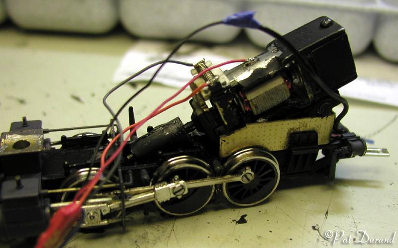
DCC Installation is not too difficult. Even though the open frame motor is not isolated from the locomotive frame, the two brushes are. You can attach the orange and gray wires from the decoder direct to the brush solder tabs after removing the original wires. I also added another electrical contact to the second and third driver tires on the left side using a phosphor bronze wiper and styrene insulator fixed in place with Black Tire ACC.
I did add add lead to the voids inside the boiler and lined the inside of the cab roof with 1/16 inch thick lead sheet scribed to simulate wood sheeting. The lead was secured with JB Kwik epoxy and the locomotive now weighs 11.7 ounces less the tender.
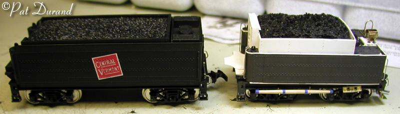
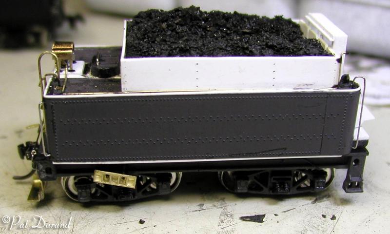
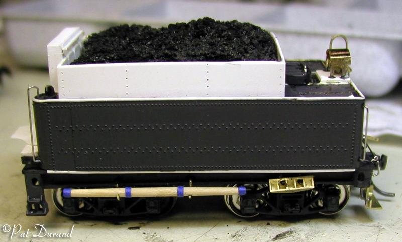
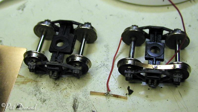
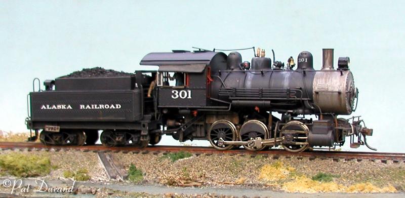
The brass tender is too long and too nice to cannibalize so it has been set aside on the rip track for future use. An IHC plastic tender from their Mogul was setting on my rip track after building Mogul #601. After considerable overhaul it makes a presentable stand-in for the shorty tender used behind #301. About 1/3 of the tank and a shortened frame were the foundation. Prototype photos and proportional dividers resulted in a very serviceable tender with a removable coal load giving easy acess to the decoder and wiring. The NP headlight that was originally on the locomotive now resides on the tender. Jeff DeBroeck is a purist who plans to shorten and modify the original brass tender so look to him for guidance on that job. I also made the tender all wheel pickup by adding phosphor bronze wipers to the tire treads on the insulated side.
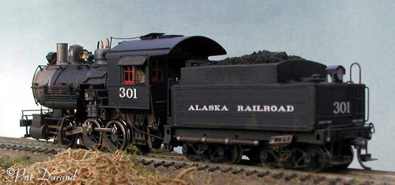
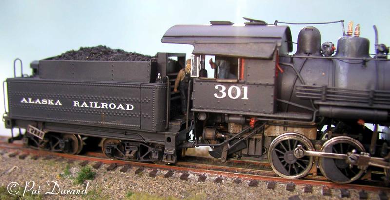
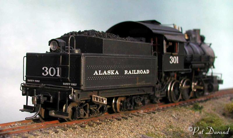
Paint represents a well worn locomotive in service, floquil grimy black over zinc chromate was dried for three days at about 100 degrees on top of my gas furnace. Weathering was done with PolyS cut with alcohol, water and lighter fluid to get various effects.
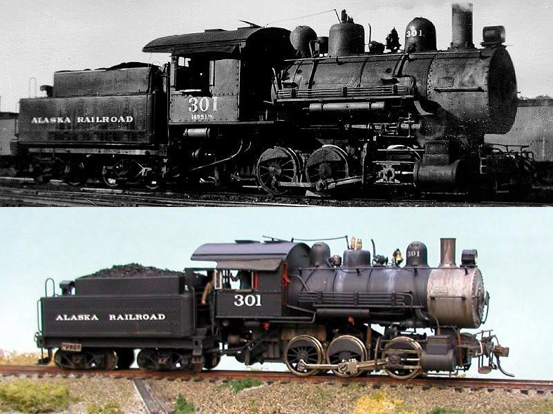
I tried to match the finished photo with the best of the prototype photos available. I convinced engineer Bill, to even put the rods down in the classic rail photo pose.
This has been a fun project. While many purist would consider "Kit bashing" a brass locomotive and putting a plastic tender behind it heresy, I subscribe to Larry the Cable Guy's moto, "Get er done!" Now I have another unique Alaska Railroad locomotive, #301.