 |
|
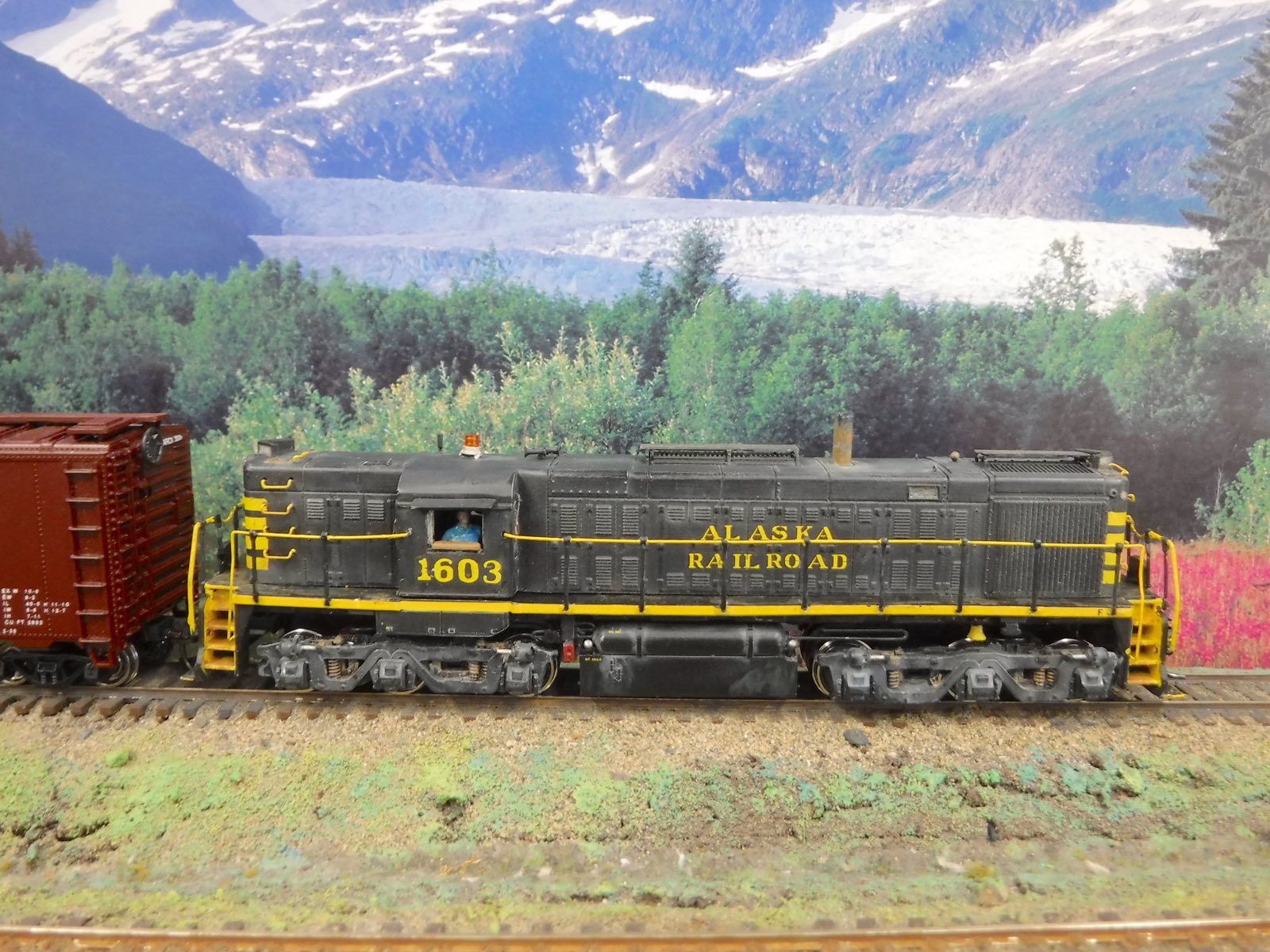
Building Alaska Railroad No. 1603 an ALCO Military Railway Service locomotive
by Patrick Durand
It has been nearly 5 years since my last addition to the HO scale Alaska Railroad locomotive roster. I have been sort of busy with the crew rebuilding ARR #557 in 1 to 1 scale. My goal has been to build one of each class of locomotive that operated on the Alaska Railroad in each paint scheme.
The motivation came about when my son, Casey sent this link.
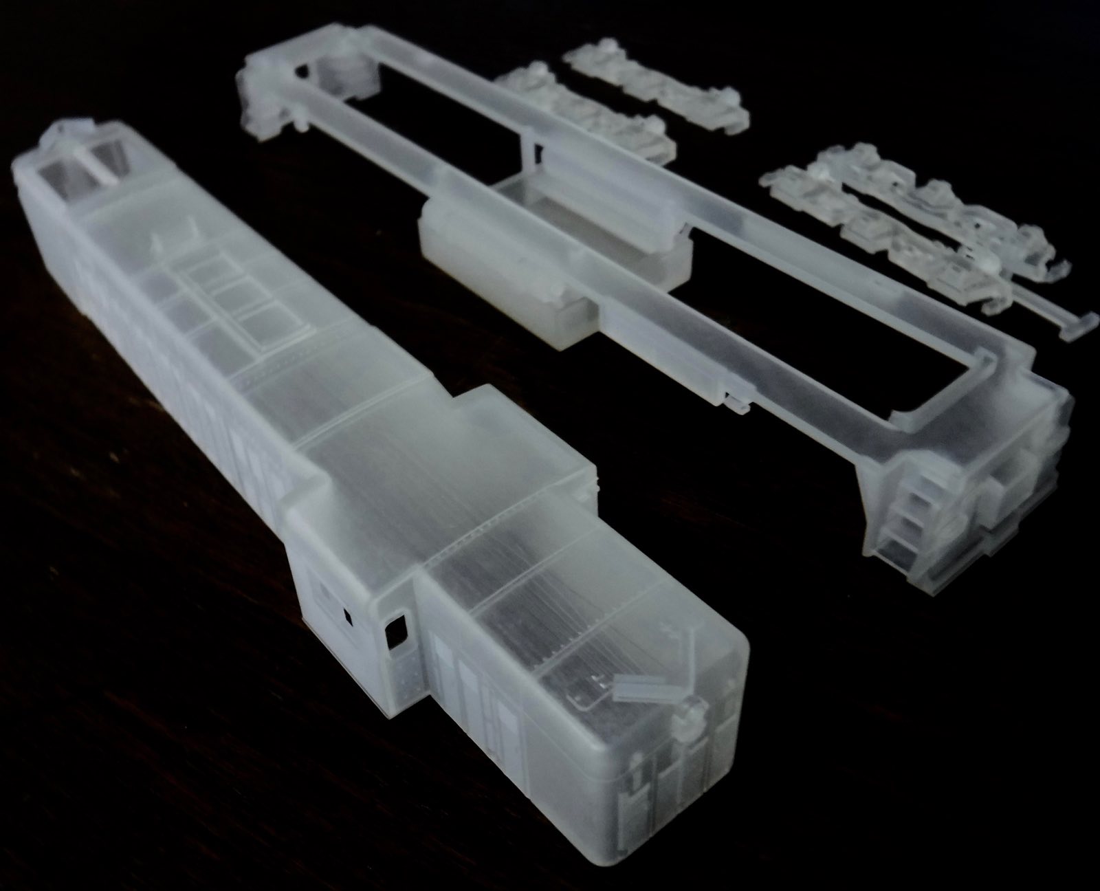
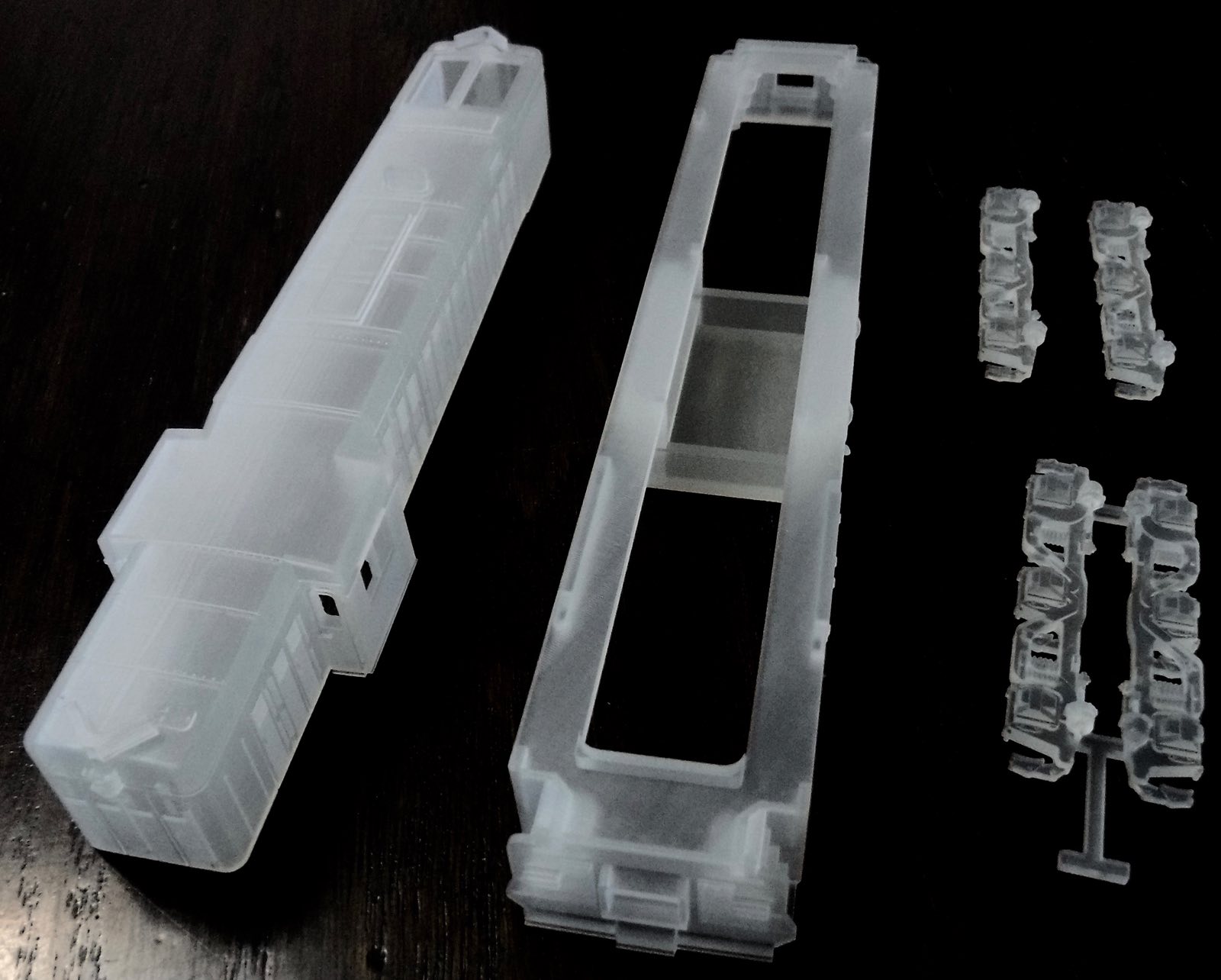
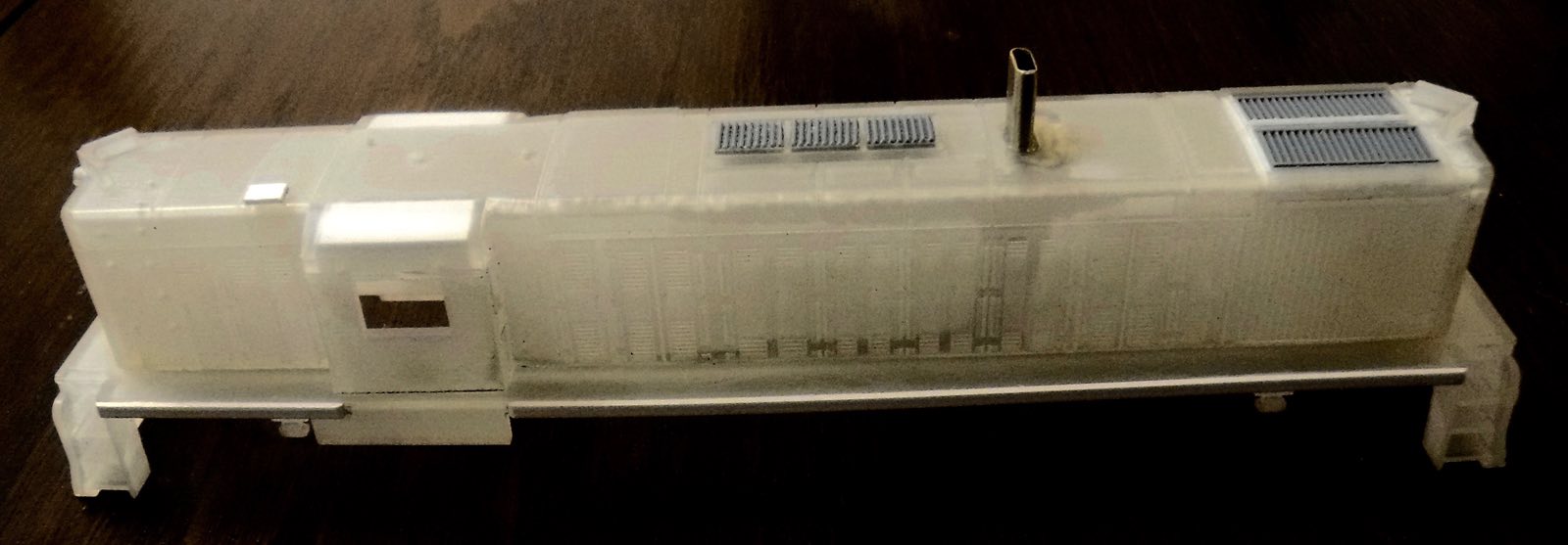
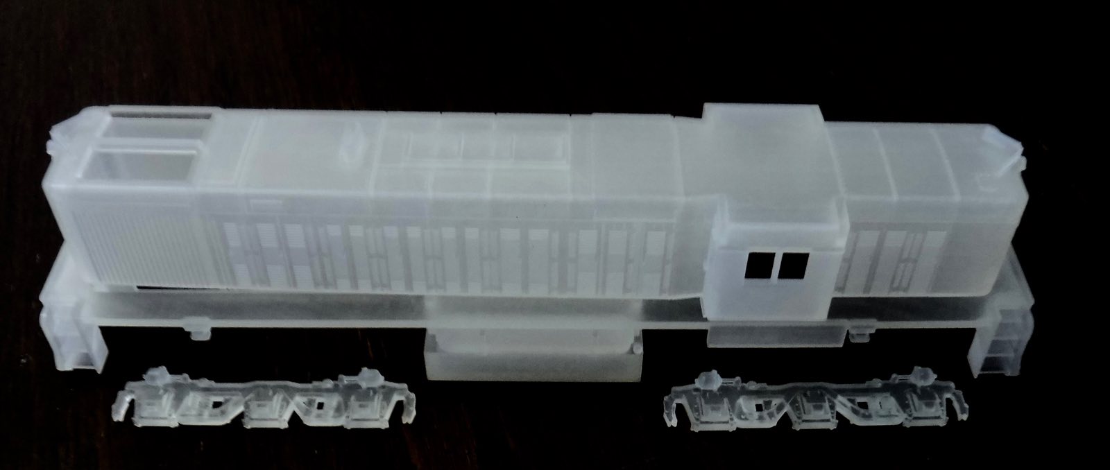
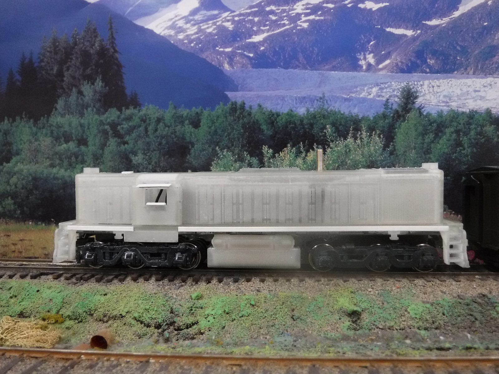
I ordered ALCO MRS-1 1/87 in Frosted Extreme Detail The Shapeways Team provided prompt service 3 D printing the body, deck and the four unique side frames and a fuel tank. It was shipped within two weeks.
On receipt the first task was to remove the parting agent? What ever it was, looked like WD 40 all over the parts, so into warm water with detergent and a soft toothbrush for a bath.
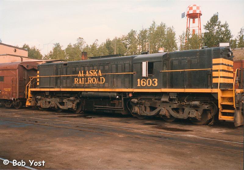
Commonly, but incorrectly, referred to as MRS-1 which was the actual designation for the EMD units built to the same military specification we will still call it the ALCO MRS. Jerry Peters retired Master Mechanic from the Alaska Railroad surveyed these locomotives at a military depot back East and oversaw transport of 12 of them to Alaska. Jerry provided a number of detailed drawings that helped identify details unique to the Alaska Railroad’s experience.
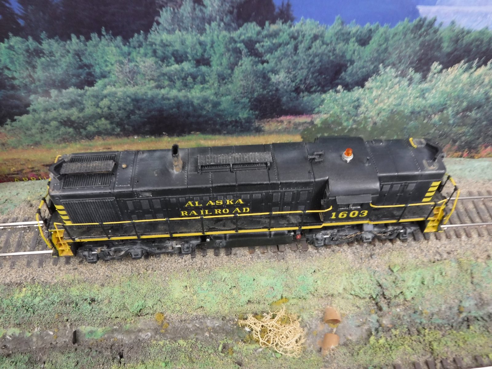
Alaska Railroad obtained their fleet of ALCO MRS locomotives during the 1970’s pipeline boom. The story is well documented in the ROSTER section of alaskarails.org. The 1600 class on the ARR received modifications before being placed in service. The walk ways were too narrow by 4 inches to meet FRA regulations so they were extended with angle iron welded on edge with gussets supporting it from the bottom. The railroad also added 10 uprights and hand rails down each side. Eventually they received yellow/orange rotating beacons and firecracker radio antenna on the cab roof. A three chime Nathan air horn adorned the top of the car body forward of the cab.
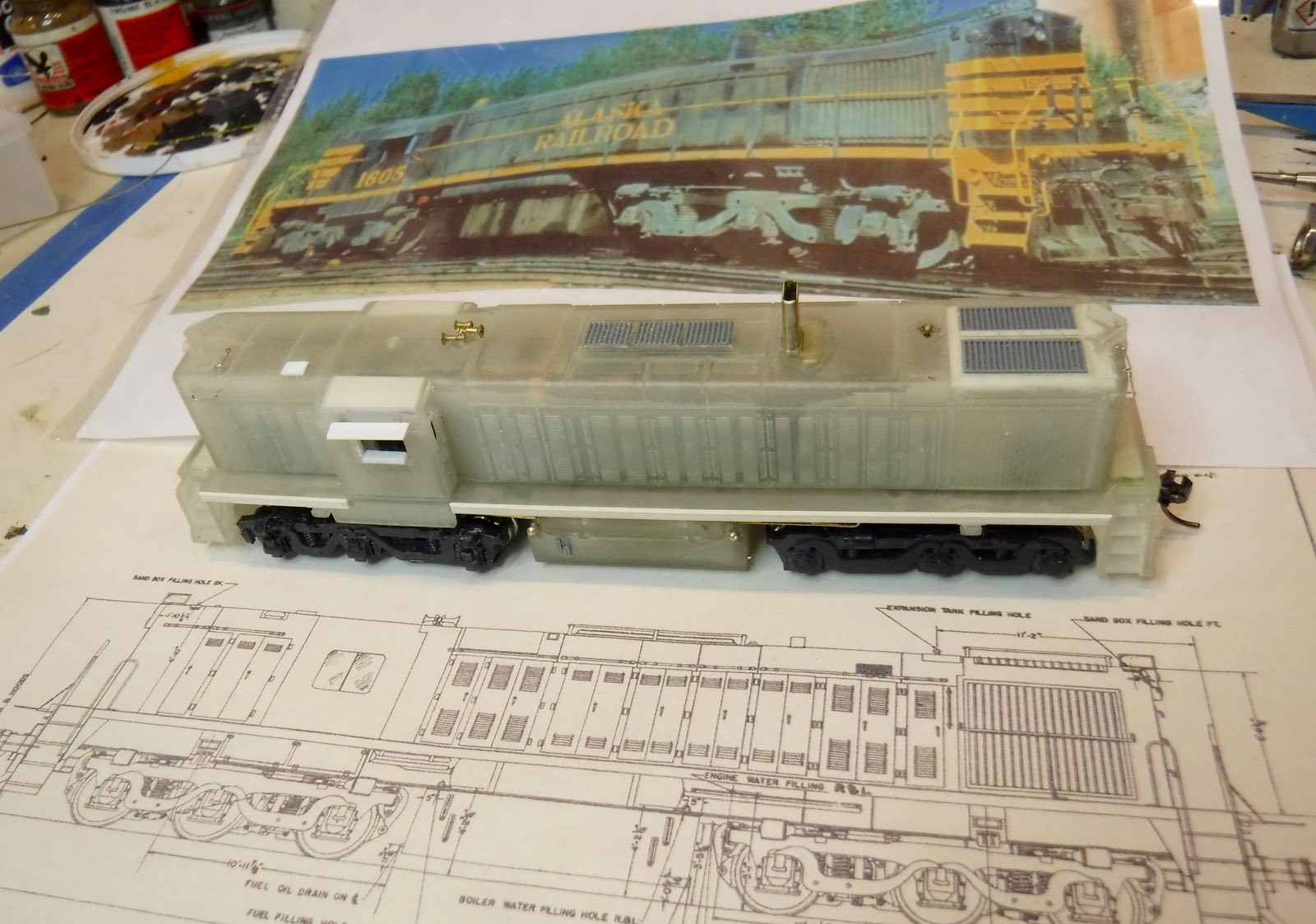
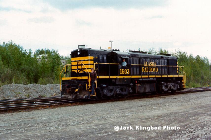
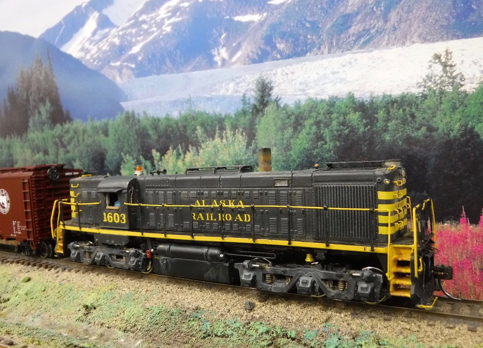
The end sills, cut levers and stacks varied over the years unit to unit. I chose 1603 to model because Roster photos of both Left and Right sides were available on alaskarails.org. Here is a photo of 1605 that shows the general weathering and modifications made over the years.
The ARR locomotives were run long nose forward so they had flag holders and clear markers at the top corners of the hood. They could run MU with EMD units but they had to be limited to run 6 or they would take up too much of the load compared to the EMD locomotives. They were popular for switching because they could load up and move quickly.
This is not a step by step HOW TO narrative. Rather these are my experiences while building a unique model starting with the new medium of a 3-D printed body shell.
I photographed 3-D the parts to study their detail and compare to roster photos on alaskarails.org. I noted the cab roof line from the side of the car body to the edge of the roof over the window did not match the ARR units. This was an easy fix described later.
The ends of the car body had small ridges running vertical where the grab irons appear in photos. My scraper tool removed these easily and then I noted that these lines provided small indentations where the grab irons were to be installed. This is a great detail if you make note of them and drill them out before removing the vertical lines.
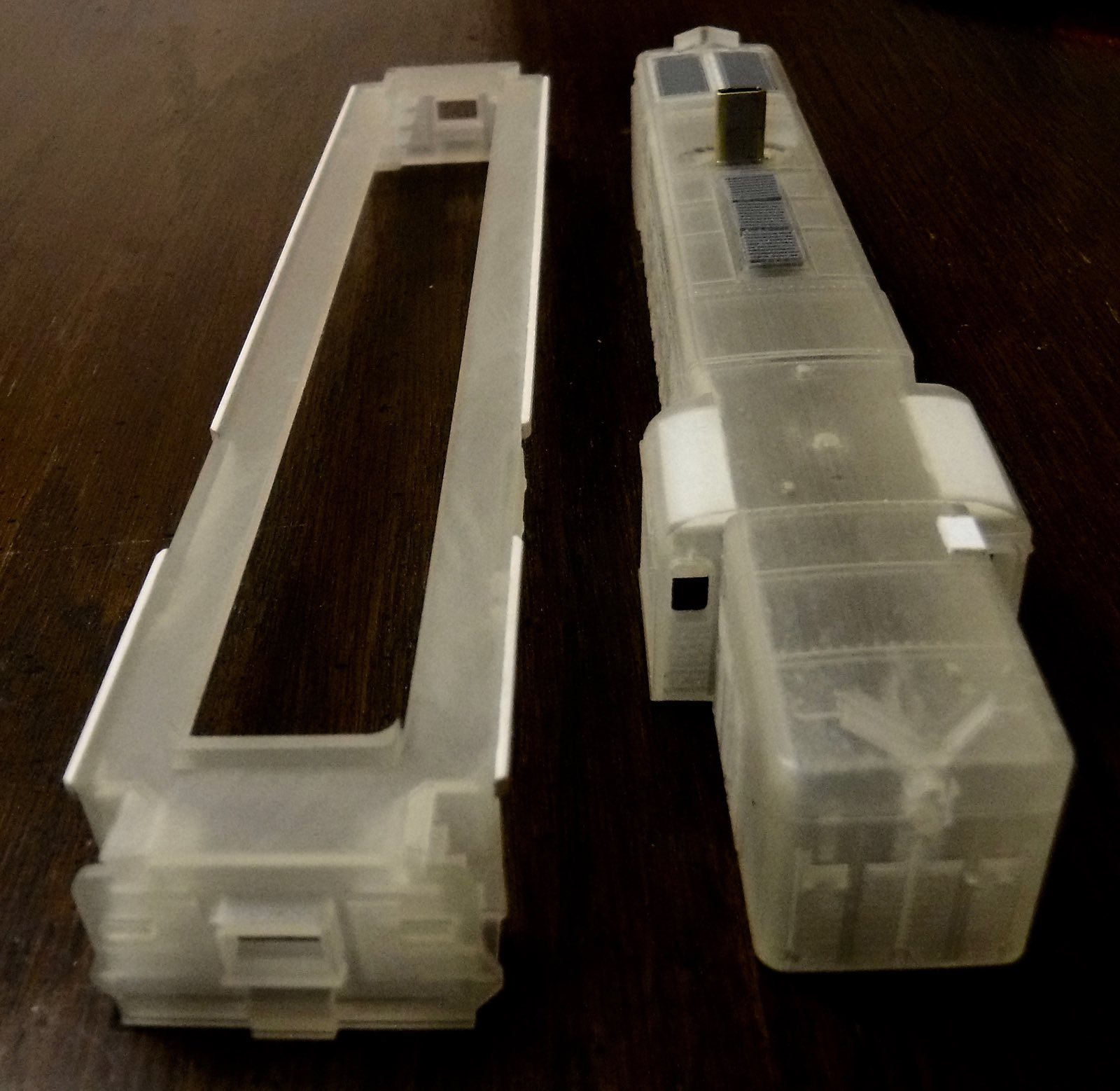
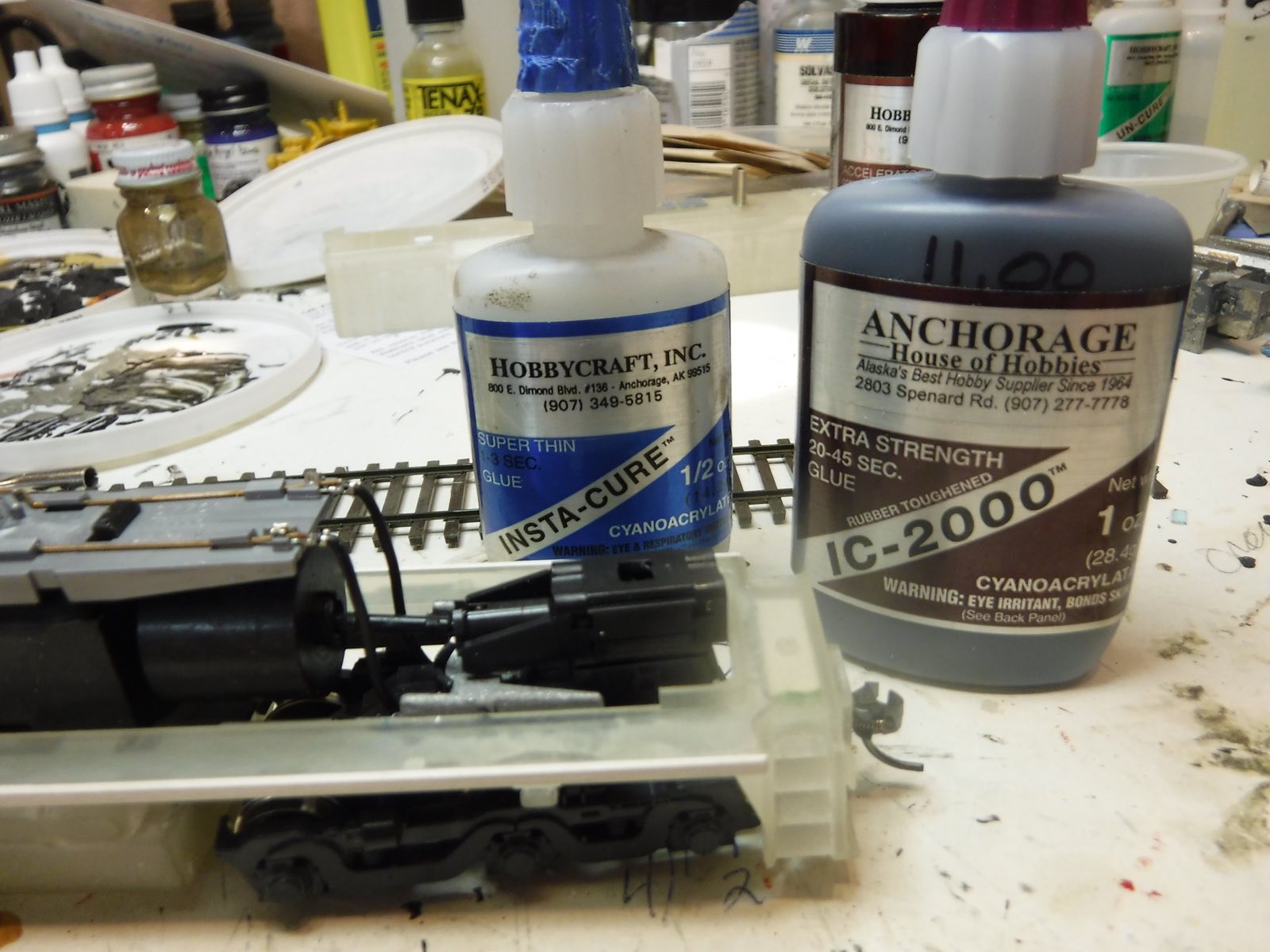
I started by adding 4” square strips of styrene to the edges of the walkways to represent the angle added by the ARR. This was not added along the bottom of the cab so it made installation easier with two shorter pieces. I used GSI gel super glue as it does not migrate and stays in place for several minutes allowing time to position the components before it cures. After it cured in place the ends were angled and sanded to match photo evidence. As insurance you can hold the assembly vertical an allow small applications of Insta Cure thin super glue to run down the under edge of the styrene and it will wick into any gaps. There were several styrene additions made to the parts.
To facilitate sloping and rounding the cab roof to match ARR roster photos, I added 4” of styrene sheet to the inside of the cab to reinforce the edge to be rounded with a large flat file. This gave a visual guide through the clear printed body to gauge progress. NOTE: I USE PROTO MEASUREMENTS IN THESE NARRATIVES SO YOU CAN USE THEM IN ANY SCALE YOU BUILD IN.
Drilled the holes for all the grab iron mounts next, by first centering them with a hand held needle press to form a depression. This was followed by a drill held in a pin vise going all the way through the shell. All the grabs are then trial fit in the mounting holes, removed and stuck to a piece of masking tape in the order that they will be reinstalled later. Areas where decals will be installed will be finish painted and decals applied before the pre-painted grab irons are installed.
Tip: Grab irons are fitted through their predrilled holes with the pins extending inside the model. After the grab is bottomed out against the car body a small amount of gel is painted on the exposed pin legs on the inside. Now pull the grab iron back to it’s proper position and the adhesive will be pulled into the hole from the back side and secure the grab iron without damaging your outside finished surface. I only remove the exposed extra pin length if it causes problems.
To represent the shutters in the roof over the prime mover and the double row over the radiator fan, I cut trimmed and installed sections of louver material from my junk box. These are also available from Cannon And Company.
The extended exhaust stack was made from two overlapped pieces of brass channel soldered together and then filed and sanded to obtain the semi round side sections. The bottom of this assembly was splayed out at 90 degrees and then inserted from the inside. This provides a strong base for the black tire glue (IC 2000) to bond to. On the prototype this was two 12” sections of fabricated tube stacked up and welded on top of the short stack. It ended up nearly 34” tall. Vertical clearance was not a problem on the ARR.
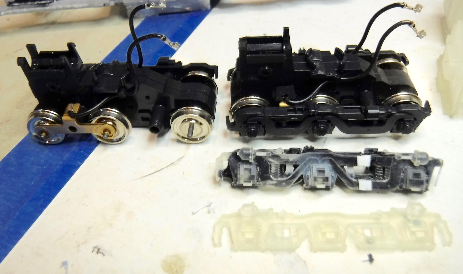
On evil bay I found a new old stock Atlas RS-4 to provide the chassis and trucks.
The parts list follows:
Details West:
Kadee:
Detail Associates:
High Tech 6023 Fuel Gauges
TDS Sugar Cube mini speaker
ESU LocSound Select Direct 73700 Sound Decoder programed 73401
Working with the clear plastic of the printed body is a different experience. You can see where the drill is going and where interior components fit. Sort of Wonder Woman’s Locomotive. When you are ready to paint make sure to do a good wash in warm soapy water and scrub with a soft tooth brush. Then blow it air dry and set it aside overnight to really dry before painting. Don’t waste your time with all the details if you are going to just hide them with goop paint like Krylon primers or Model Masters. I suggest Tamia light gray primer and semi-gloss black. These are very fine pigments that lay down very well. Yellow stripes and the Alaska Railroad are decals already available in various sets. You will need to piece the stripes and numbers together.
The 3-D truck side frames are correct in the axle spacing. The axles are not equally spaced because there are actually three traction motors suspended between the axles. Two are back-to-back and that means the axles are farther apart.
However, in order to use the Atlas RS-4 chassis and trucks some adjustment is required. The RS-4 axle spacing is about 8 inches longer on the end with two traction motors. My fix for this is using an orbital sander mounted in a vice. I removed the face detail from the Atlas HO scale three axle truck to make a sub foundation. Then I removed material from the back of the 3D printed side frame. Match two of the axles with the journals in the 3D printed side frame, and cut the odd mismatched end with one journal free from the casting. I lined up the free journal and glued it to the sub frame over the third axle end.
Using flat styrene stock I patched the missing sections in the 3-D side frame. With paint and weathering you will not notice the fix. Remove the cast on brake hanger and brake shoe at each end to gain clearance. They look funny and on the prototype are much further inboard out of sight. The side frames are now thicker and are further out under the walkways. Actually that is correct because the prototype was built to accept axles with wheels set at 6 ft gauge.
The 3-D printed headlights will shatter if you try and drill or ream them out to accept plastic lens inserts. Best to just remove them and replace them with white metal Pyle Dual headlight housings.
The RS-4 chassis fits well under the 3-D deck. But it leaves the deck and body one scale foot too high. The solution was lowering the body bolster by one foot. Using the cut off wheel in the FOREDOOM tool The body bolster was lowered by cutting it from the frame, removing material and gluing it back with Tire Glue ACC. This puts the pilot steps, coupler pocket, fuel tank at the proper height over the rail. Also pushed the trucks down a foot so they clear the frame properly when the body and deck are attached.
The resulting height over the roof of the cab and car body is now 12’ 4” right on with the drawings. The stack is a scale 34” high.
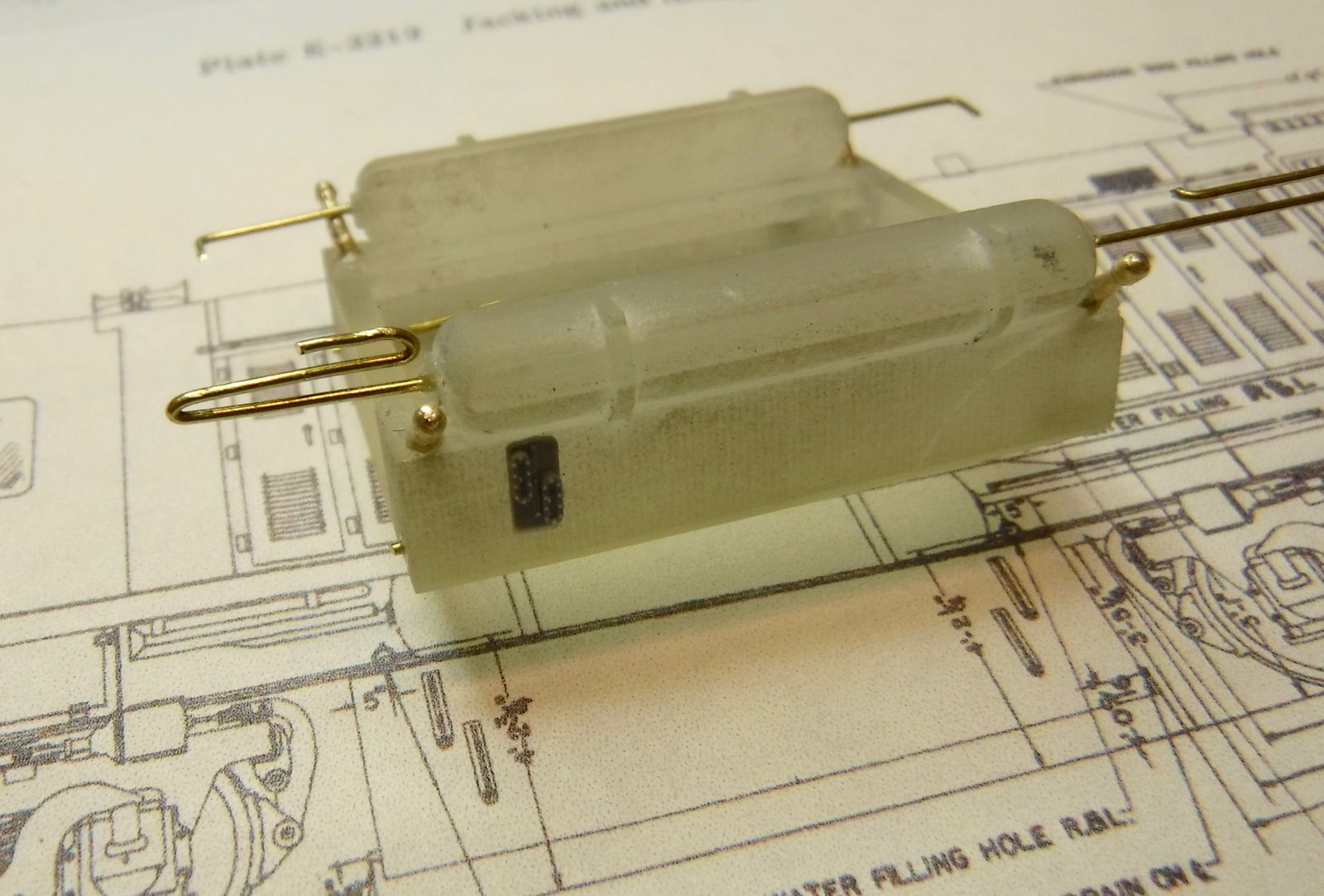
In order to fit the fuel tank, I used my trusty Foredoom tool with an abrasive cut off tool to narrow the RS-4 belly tank to accept the 3-D tank. Then I drilled clearance holes in the 3-D tank so you can reach through it to remove the motor mount screws if needed. I attached the 3-D tank with a single 256 screw in the middle bottom of the tank with a matching hole drilled and tapped into the white metal frame above. Finish this off by adding lead to fill the plastic tank. I did this with strips of pure lead solder mashed into flat bars in a vise and then cut to length and held in place with ACC.
Some of the 1600s came with steam generators in the short end and the tank had two compartments one for water and one for fuel. There were four filler pipes. We are modeling as it was later in service when the ARR added by-pass pipes on the bottom and connected both sections for one big fuel tank since they did not use the steam generator in the nose. My modification included removing one set of fuel level gauges. Also added the plugs in the drain holes in each bottom corner.
When outfitting the car body with a speaker I did away with the front body weight. The sugar cube speaker is secured on its side to the top of the gear tower with Walthers GOO. This is easily cut away with a sharp blade if you need to remove the truck in the future. The rear body weight is fixed with G00 to the remaining stubs of the rear truck bolster. If you have components that do not want to stay in place like the walk ways over the roof shutters, just little dabs of GOO from the end of a needle on each mating surface will provide a flexible and secure bond after about 3 minutes. One of the problems with the 3-D printed components is their resistance to common adhesives.
After operational testing, I replaced the Atlas circuit board with an ESU73700 LokSound Direct replacement decoder. I specified the 73401 sound program for the ALCO 244 12 cylinder engine. Out of the box this will support LED lamps without using resistors. Accessory pad 3 is programed for a slow rotating beacon. All of the LEDs are fixed to the chassis and aligned so when the body is dropped in place they illuminate through light tube lenses in the headlight. NO WIRES to disconnect.
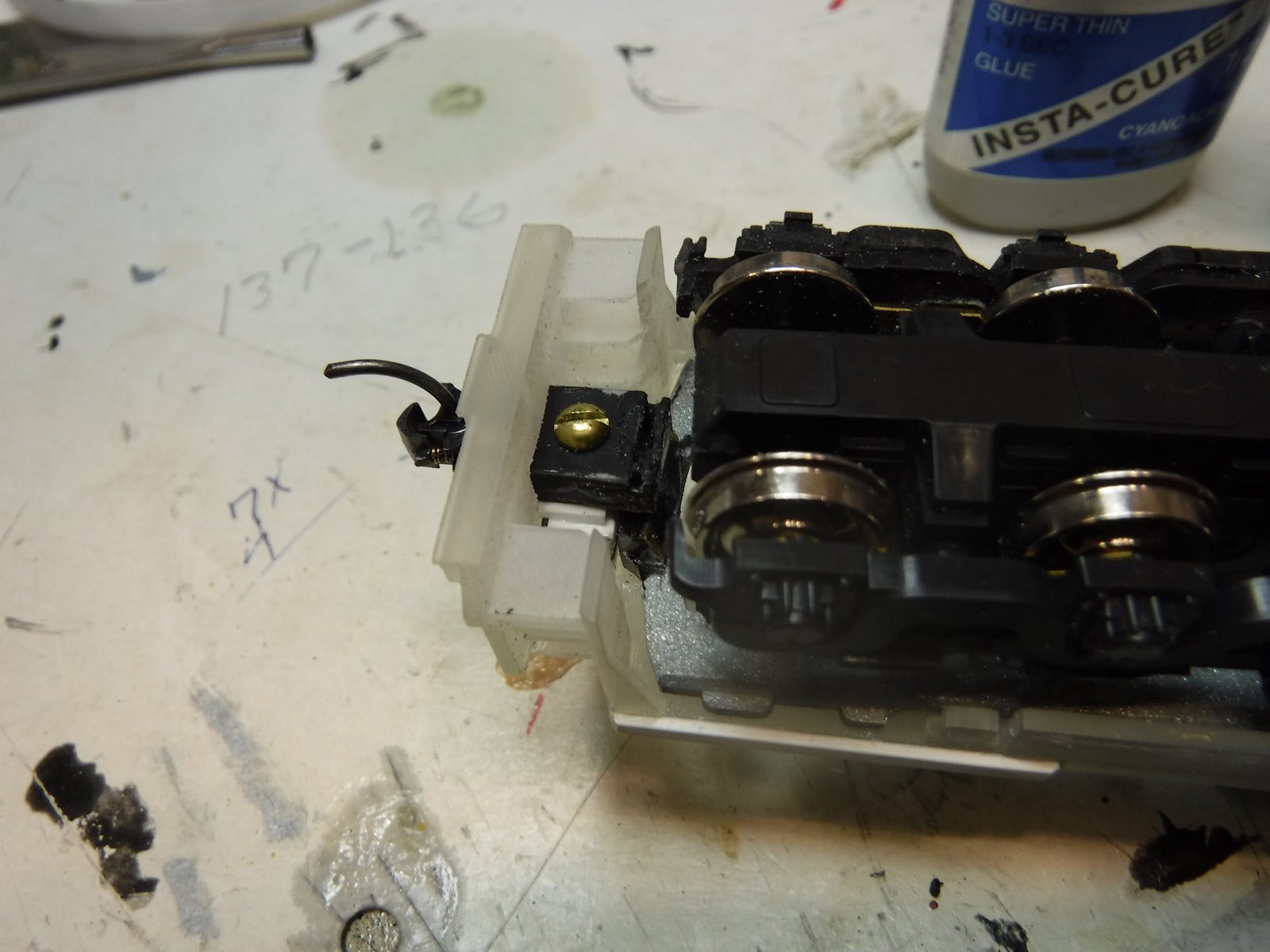
Let the coupler box secure the chassis to form the body mount. Make up a set of couplers in a plastic coupler box and then file the 3-D end sill until you have a friction fit. Now set the chassis in place under the deck and you will need to elongate the drawbar opening to get the coupler down to proper height. Use a Kadee #22 medium overset shame coupler to eliminate some of that work. When the coupler height is right, fill the void above the coupler box with styrene shims. With the coupler box in position there will be about 1/16th inch vertical space between the top of the coupler box and the bottom of the chassis to fill with styrene shims glued to the chassis. Properly done, you can remove the coupler screws, pull the coupler with the box out each end of the chassis and lift the deck off.
I used Tamia paint light gray primer and semi-gloss black on the 3-D parts. You must lay down several light coats at 90° to the surface in order to get penetration into all the cracks and crannies. If not, light will shine right through your paint job at every seam and joint. Decals were applied in stages and pieced together. I made liberal use of Solvoset to settle the decals into the paint and after drying over night applied light sprays of Dulcoat. Then you can apply more decals without disturbing the first application. The goal is to represent 1603 in Service.
The hand rails on the end platform came from an Atlas GP in my junk box. They are close. The side rails were done just like the ARR did it. I found some old Athearn stanchions and fixed them into holes drilled into the side sills. I use spring steel wire to bend up hand rails in two sections for each side following photo references. With the car body in place I marked where the railing intersected the cab. Then I removed the body and fixed all the railings in place with Insta Cure ACC applied with a needle next to the joints at the top and bottom of each stanchion. When this cured I painted both the hand rails and the stanchions. The intersection points with the cab were then verified and holes drilled in the cab wall. A piece of card stock was placed between the ends of the hand rails and the sides of the cab as the body was lowered into place. The card stock was slowly removed and the ends of each hand rail penetrated the wall of the cab about 1/8 inch. Being spring steel they were pre loaded to bottom out against the side of the cab and that is what holds the body to the deck! Do not make a habit of lifting the locomotive by the car body, grab it by the fuel tank.
Liberal use of Armor Wash, Doc O’Brians weather powders and various washes, with occasional touches of clear to represent wet spots pops out the details for inspection and presents a well used near retirement version of Alaska Railroad 1603. I am pleased with the result and that is what counts. One more locomotive in the HO roster.
3-D printing hopefully will bring more unique diesel locomotives to the modeling bench. Maybe an EMD MRS-1? Embrace them as a new modeling experience.
Patrick Durand
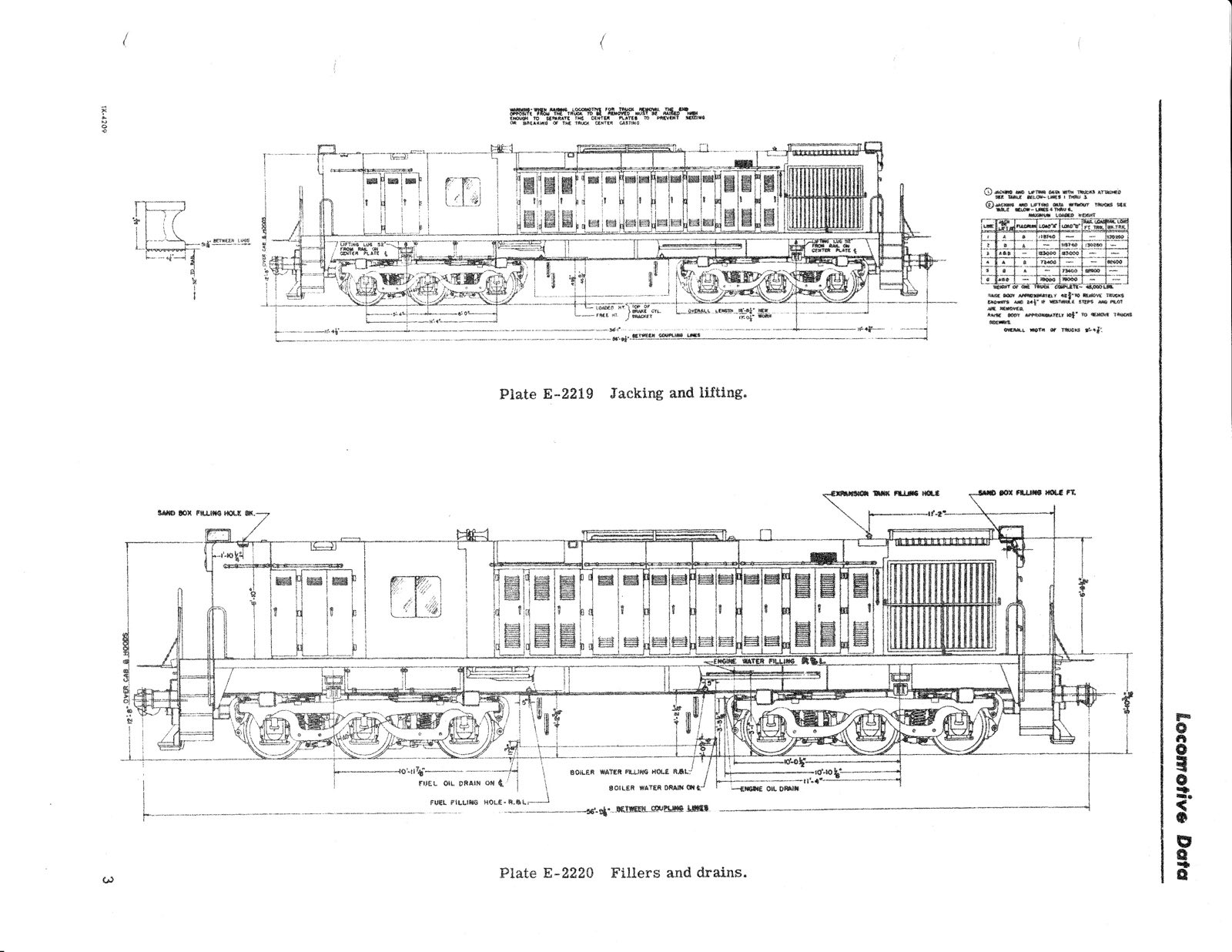
Drawing of MRS #1603