Modeling Alaska Railroad F7A #1506 cir
1972-1986
By Pat Durand
See also:
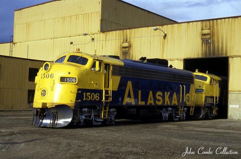
Alaska Railroad #1506 EMD F7A Builders # 19045, along with 1507 and 1508 composed
the second delivery of new units placed in service in January of 1954. They
did not have the extended fuel tanks of the first batch of 6 units delivered
in December 1952. On arrival they were in the Blue and Yellow/Gold passenger
scheme with the Mt. McKinley Route logo on the nose.
By 1964 the Black and Yellow freight paint scheme was being applied to many
of the F units.
In 1982 she was trading her Black and Yellow freight paint job for the new
Blue and Yellow bill board scheme. This paint job was retained until her retirement
and sale to Mountain Diesel Transportation in 1986.
.
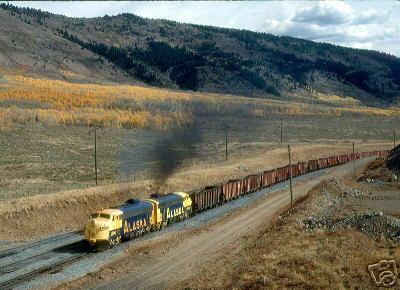
After leaving Alaska #1506 had a short afterlife spent with #1508 hauling phosphate
rock towards the connection with the Union Pacific's Dry Valley branch in eastern
Idaho on October 3, 1988 as photographed by Blair Kooistra. The units, owned
by Mountain Diesel Transportation, were on lease when the two locomotives ran
away unattended and derailed.
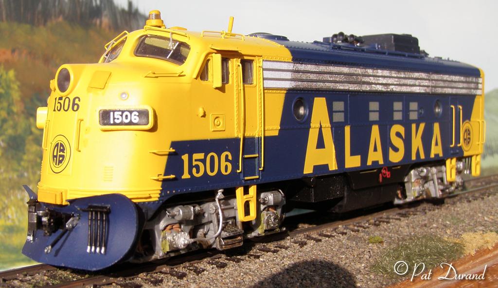
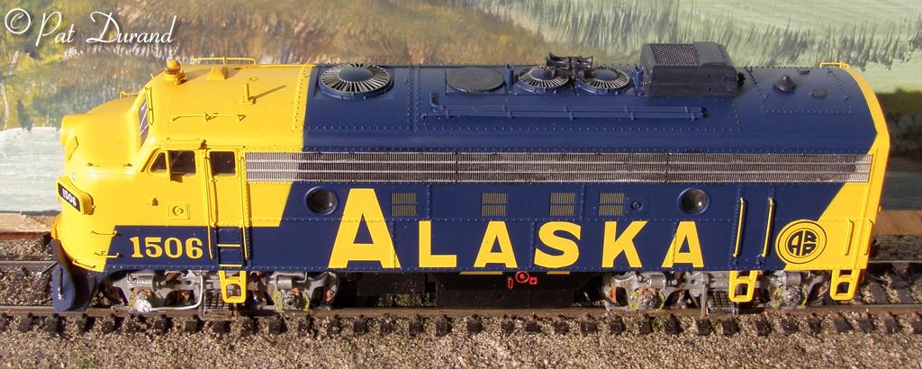
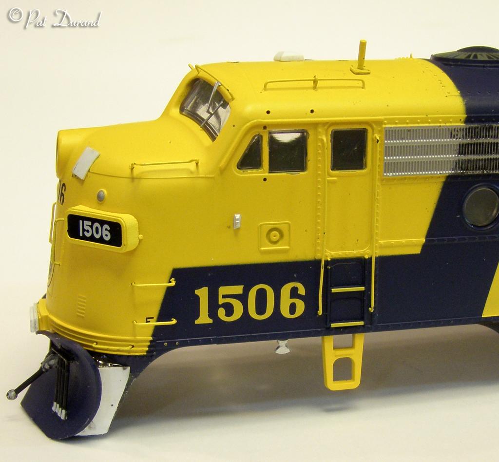
Building the Model of #1506
My model of #1506 started with the Bowser Executive Line F7A in HO scale model.
Alaska Railroad #1506 came equipped with SOUNDTRAXX DCC. This is the best effort
so far at producing an off the shelf Alaska Railroad version of the F7 family
in the blue and yellow billboard Alaska paint job.
Bowser gets good points for the following features:
- Amazingly, by chance or design, the hand rails at the doors terminate at
the bottom of the door and not at the frame! This is unique to Alaska Railroad
F units which had the hand rails shortened after they found the stock mounting
at the frame level came into conflict with the service platforms in the new
engine service facility when the first units arrived in December 1952.
- Good paint and lettering in proper colors. (Rail Box Yellow and B&O
Royal Blue are close matches)
Grab irons and hand rails in proper positions on nose roof and rear.
- Roof cooling pipes for air compressor are in correct location.
- The etched stainless, wing mirrors and sun shades are very effective and
strong when pressed into position and then secured with a little Crystal Clear.
- They made a good attempt at the plow but no cigar. It is OK for the mass
market and has the correct overall shape. The dispersion angle is too shallow
and the support on the back extends the plow a scale 8 inches too far forward.
There is a fix however and I plan to order 10 of the plows for stock as kit
bashing fodder.
Here is a list of shortcomings:
- Operationally, out of the box the locomotive will foul on a properly installed
Kadee uncoupling magnet. These magnets set slightly above rail head when installed
with the Kadee coupler gauge on Code 100 rail. The lettering (Stewart 74475)
on the bottom cover plate of the truck gear box will hit the magnet. A call
to Bowser assured me this truck has been in production by Stewart for 9 years
and " is not a problem".
My experiences with Stewart locos goes back to the days when the truck gear
box cover plate said (Made In Japan Kato) and they had more than enough clearance.
Several of my ARR F units have this old power train and it is excellent. Once
the bottom cover plate is fixed the new chassis is also a great performer.
The solution with the new truck is to pry off the cover and sand away about
half of its thickness and reinstall. Problem solved unless you break the cover
in the process.
- The nice paint job is marred by the fact they did not remove the ugly die
parting lines that wrap horizontally around the nose on each side of the headlight.
There is no way to fix this and save the paint job, so I just ignored it.
- The couplers supplied are Kadee imitation standard shank couplers. I chose
to replace them with Kadee #153 short shank scale couplers with whisker springs.
After removing the original funky plastic clip retainers, the original coupler
box accepts the new couplers. Cut the trip wire off the front coupler because
it will interfere with operation. (If you plan to switch with the front coupler
put another buffer car with out a trip wire next to the loco nose so it does
not interfere with the plow.) I discarded the retainer clips and simply tapped
the coupler mounting hole 2-56 and used a single 2-56 screw to mount each
coupler. This eliminates chancy prying and prodding those pesky retaining
clips.
With all the reference material available the following missteps could
have been avoided:
(Note: All the measurements given are in real inches so you can convert
to whatever scale you use.)
- The snow plow provided is a good starting point to simulate the large plows
built by the Alaska Railroad Anchorage Shop crew.
Pull it strait forward and it will break off its two supporting pins to reveal
a heavy frame on the back side that prevents it from laying properly up under
the anti-climber. With a zona saw make a vertical saw kerf on the centerline
up the back side of the plow. DO NOT cut all the way through. Now fold the
wings in to a tighter angle and carve away the supporting frame so that it
fits closer to the anti-climber. At the center bottom the frame should be
reduced so only the thickness of the plow extends beyond the pilot on the
cast body. When you have it right, the top of the plow should fit right up
to the anti-climber on each side of the buffer plate. When it fits right glue
it in place with MEK and clamp it until it cures overnight. Finish the job
by adding new braces form fitted behind the plow up to the bottom of the anti
climber on each side. To finish the plow install with a cut lever on the right
side extending through a hole in the brace. Check photos for the details here
as there are variations from one loco to another.
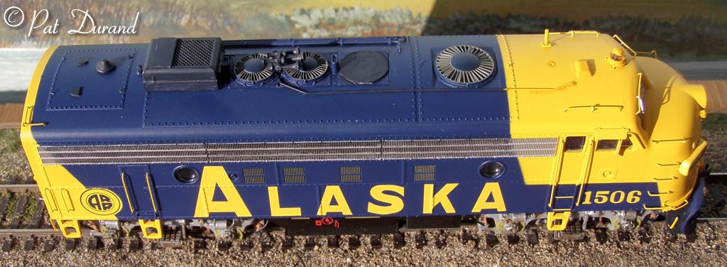
- The winterization hatch is too small and does not match any EMD part I
am aware of. The prototype is 58" long 42" wide and 22 inches high.
Operationally this is two EMD hatches stacked on top with shutters inside
that are manually set for either Winter or Summer with handles on the left
side of each box. The screened opening is 27 inches wide and 30 inches long.
There is a two panel door cover with piano hinges, usually stored in the folded
back open position clear of the screened opening. These two door panels are
each 16" X 29.5". (This feature is best modeled with a Details West
WH-164 modified by adding a riser of square styrene square strips measuring
10" high down each side. Offset these strips 1" out to represent
the flange joint between the top and bottom sections. Fill the void between
the strips front and back and add a heat deflector made of .010 styrene to
the front of the hatch where it sets next to the exhaust stack. Create the
two doors from .010 styrene and fold them back in the open position. You will
have to file the rear fan flat to install the housing.)
- With only a few exceptions the front fan on ARR F units was eliminated.
In some cases the opening is covered with a flat circular steel panel and
in some it is slightly conical. On 1506 just a disk of .010 styrene will do
the job after you file the fan flat.
- The Firecracker Antenna is in the wrong location. Remove it by pressing
it out from the inside. Drill a new hole 30" to the left of center from
the original location. Reinstall it perpendicular to the curve of the roof,
NOT vertical, as one of the last additions to the model.
- The ARR used Leslie 5 chime air horns in a variety of configurations so
check your prototype photo for location. These were mounted between the remaining
two fans in later years to keep them from freezing up with snow. Now connect
the horns to an air supply by simulating the line from the horns out to the
right side of the fan bank and forward bypassing the Dynamic fan. At that
point it bends toward the center and connects to the air supply where the
original forward facing horn had been installed. (I installed the Details
Associate AH-327 5 chime horn and simulated the air line with about 3 real
inches of .010 piano wire bent to shape.)
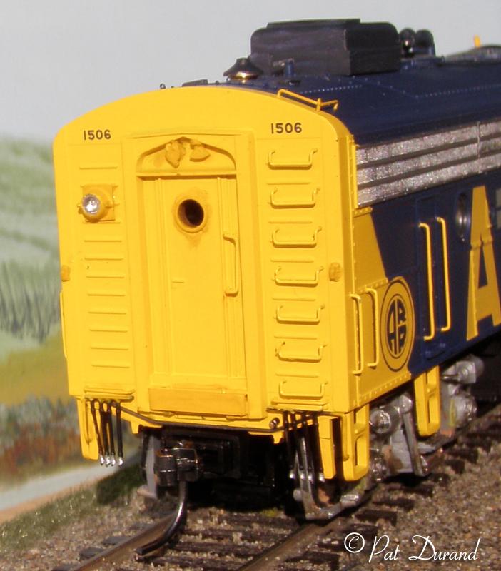
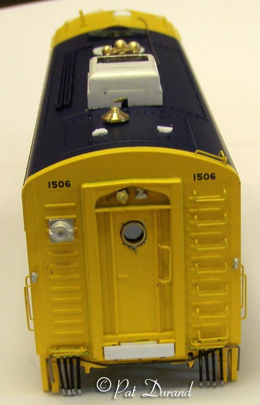
- The rear door window is round not square in 1506. Use a piece of brass tube
with a 13" OD and then re-drill the opening to a press fit for the tube.
Polish the exposed end of the tube so it looks like a rubber window bezel
the cut off about a 1/16 inch section and press it into the hole.
The following features were not included on the model:
- The cab ventilator is made from a block of styrene 15" long, 9"
wide and 4" thick. Using a long piece of stock size and shape one end
to this general size and then taper it so the top surface measures 4.5"
by 10". Attach another piece of .010 styrene 5" X 10" to the
bottom of the ventilator to create a stand off. This is installed with the
left edge just right of cab center and the front long edge behind a line connecting
the front edge of the cab doors. There is a large roll bar just forward of
the doors that supports the roof and the vent is right behind it.
- A back up light is mounted on a plate to the left of the rear door. This
is located over the third rib from the top and spans between the 2nd and 4th
rib. Details West Back up Light BL-162 does the job. After it is secured and
painted drill it out to accept an M.V. Products # LS-19 or similar lens.
- MU connectors are needed on both the front and rear of the locomotive. Detail
Associates set 101507 provides a variety and you can install one to the left
of the headlight. Install another in the top of the rear vestibule opening
as far to the left in the opening above the door as it will go. While there,
also install a Details West SL-172 Step Light just to right of center in that
opening above the door. Back at the front cut a piece of paper or .010 styrene
12" wide and 13" long to create the hatch cover for the MU connector
to the right of the headlight. This piece should be thinned down and pre-curved
to follow the contour of the nose before application. Refer to photos for
prototype location.
- Install Details West SL-172 Step lights in the bottom edge of the car body
below each cab window. Drill a slightly oversize pilot hole up into the plastic
and then glue the light shank in. These are actually ground effect lights
to assure the crew of their status, either moving or standing still, when
they were next to another moving train.
- The ARR moved the batteries from below the frame in front of the fuel tank,
to a warm location inside the car body. Racks were built into a box at the
rear of the car body where a steam generator could have been installed. To
clear this area of explosive battery gases there are three vents on the roof
which are not commonly modeled. Two small air scoops measure 1.75" inches
high, 6.5" long and 8" across the mouth. The scoop tapers back to
a 2.5" radius at the end. Cut these one at a time from strip styrene,
rounding the small end while still attached and then part it off to length.
Now to position these vents. From the rear of the locomotive: The right vent
faces forward on a centerline 16 inches from the right edge of the hatch.
The open front of the right vent is 28" from the rear edge of the hatch.
The left vent faces to the rear on a center line 24" from the left edge
of the hatch. The open end is 17" from the rear edge of the hatch.
The circular stack is 14" in diameter with a 4" diameter piece extending
up 1.25 inches in the center. The top of the 4" diameter extension is
10" above the rear hatch cover. The stack stands off from the roof 2.5
inches on an 8" diameter tube. Are you confused yet? That means from
the widest point of the 14" diameter to the base of the 4" diameter
extension there is a rising slope with a total vertical rise of 6.25 inches.
I use a piece of round brass stock and part these off on my mini lathe free
hand with the scale calipers in one hand and a finishing file in the other.
You can probably do the same with your drill press and a piece of plastic
round stock. Just make it out of one solid piece of rod, there is no hole
in the middle and leave it long enough on the bottom to fit in a hole drilled
in the hatch cover. Locate the mounting hole left of center 31" from
the left edge of the hatch and 43" from the right edge of the hatch and
20" back from the front edge of the hatch.
- While working in this area use a sharp #11 blade and cut a shallow notch
in the top of the water filler cap. Flatten a piece of fine brass wire into
a flat bar and glue an 8" X 1.5" strip into the notch in the filler
cap. This gives the crew something to whack at with a hammer when trying to
get the pipe cap off.
- The cab beacon is located on the centerline straddle of the casting mark,
clearly seen in the model, indicating a weld seam from side to side between
the wing windows. The Details West Flasher Beacon RB-106 has the correct base
and makes a strong installation when the lens shank is extended through a
#52 hole in the cab roof. The yellow or silver cap seen on these is problematic
in getting the right shape and having it stay in place. I used a piece of
round styrene rod to form the cap and then parted it off the end of the rod
and glued it in place with MEK on top of the lens. Paint this assembly before
installing the shank through the roof and gluing it from the inside.
- Minor but distinctive are the flag holders at the rear corners adjacent
to the 6th rib up. Details West FH-323 are appropriate. On 1506 there is also
one mounted on the left side below the wing window just forward of the sander
cover.
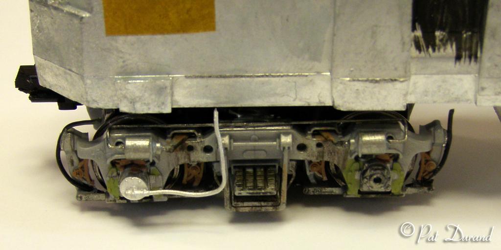
The following additions and modifications can be made to the chassis:
- Add airlines to the brake cylinders with .010 spring wire. Bend the wire
so it spans the distance between the outer ends of the brake cylinders. I
form a U in each end of the wire so it can be inserted into holes drilled
in the outer ends of the brake cylinders. A few kinks will make the wire lay
down on top of the truck frame and terminate in each cylinder. A little ACC
will secure the wire to the top of the truck frame.
- Sander Hoses made from black or gray insulated single strand brass wire
can be inserted in front of the brake shoe and behind the brake adjuster bar.
You may wish to pass a drill bit through this path to make it easier to insert
the wire "Sander Hose".
- Details West SR-284 speed recorder is properly mounted on the left front
journal of #1506. The speedo line runs horizontal back and then loops up to
the bottom of the frame. I usually lightly tack it to the truck side frame
as high up as possible and let it disappear.
- Extend the front buffer plate a total of 4" with layers of styrene
to match photos. At the rear fill the void under the door with a styrene block
and add a 4 " thick buffer plate of styrene to extend out over the rear
coupler location.
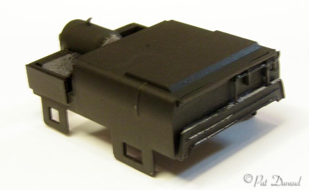
- When the batteries were moved inside the car bodies the space they had occupied
was modified and storage boxes marked "FROG" were hung on each side
of the loco. To access these boxes a portion or all of the skirt was removed.
In the case of #1506 the skirt area from the external DC electrical plug back
to the Fuel tank was trimmed off flush with the bottom side batten. This is
easily done while the body is off the frame using a sharp knife and files
removing plastic to match the prototype photos.The fuel tank cover snaps off
and the casting below allows removal of the bottom of the forward portion
where the batteries had been. The "Frog" boxes can then be simulated
with styrene and an air tank fabricated from plastic rod is added with some
plumbing. The tank assembly still snaps on and off.
- Cut levers bent from .010 spring wire can be made in one piece and applied
at the rear.
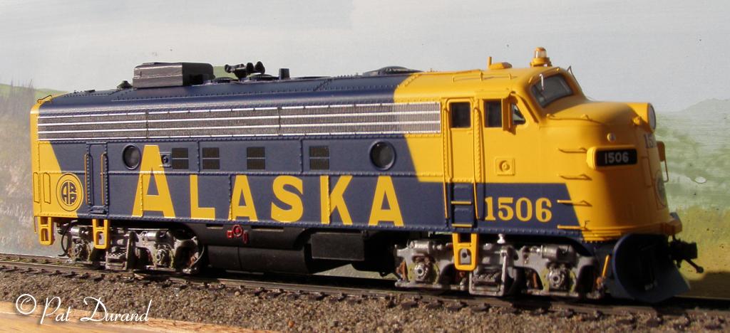
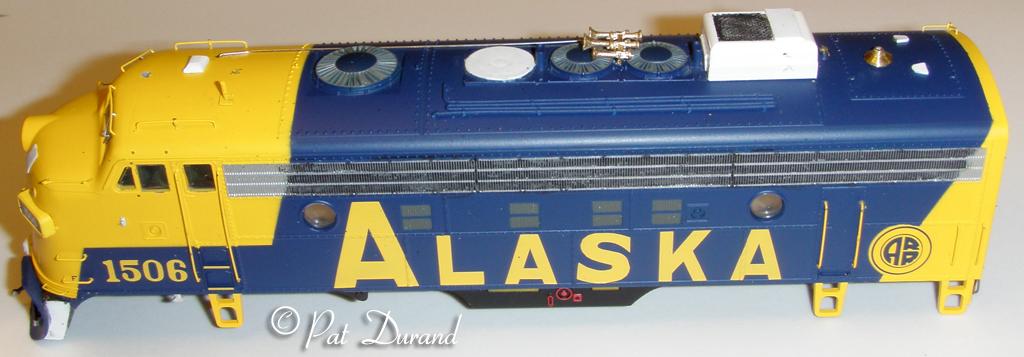
A selection of photos of the model before and after painting are provided
here for further clarification. I hope you find this upgrade modeling project
worthwhile just as I did.
Back