Pat Durand's E9 Numbers 2401 and 2402
Modeling the Alaska Railroad E9A Locomotives #2401
and #2402
By Pat Durand
The Prototypes:
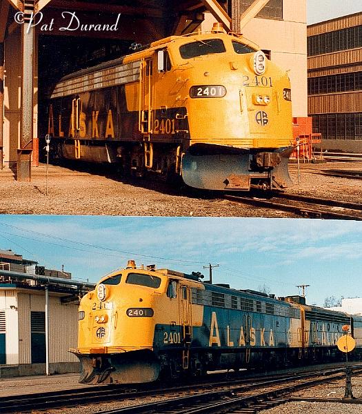
Alaska Railroad #2401 originated as EMD builders
No. 20494 in 9/55 as Union Pacific #957. Locomotive became AMTRAK #430 in
4/71 and was acquired by the ARR in July 1981. Retired in 1986 she went on
to become Wisconsin Southern #10A in 1992.
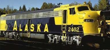
Alaska Railroad #2402 originated as EMD builders No. 21605 in 1956 as Milwakee Road #202A later renumberd 32A. After aquistion by AMTRAK as #434 she was purchased by the ARR in July 1981. Retired in 1986 she went on to become Wisconsin Southern #10C in 1990.
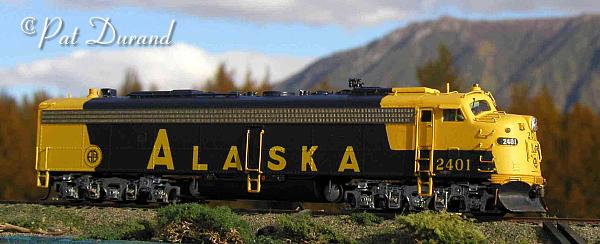
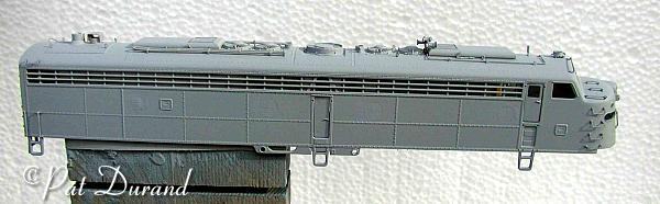
Both #2401 and #2402 were rebuilt by the Alaska railroad with 645 engines, smaller wheels and freight gearing of 55/22. They were usually assigned as the lead unit on Anchorage/Fairbanks express passenger trains #1 and #2, followed by a mix of FP7 and F7 A&B units and HEP cars as needed. The immediate spotting feature differentiating #2401 was the use of surface mounted twin Pyle headlights.
The Models:
The Lifelike Proto 2000 E 8/9 undecorated kit is the basis for Alaska Railroad E8 units #2401 and #2402. These tips apply equally to any of the F7 A and B units which share many of the same details. At the risk of preaching to the choir, I have written these notes so that a novice may learn some of the basic techniques employed in the use of adhesives, painting and fabrication while avoiding a few of the hard learning experiences that can be a real turnoff to production. I consider modeling a serious art form. My goal is to capture the character and essence while preserving the history of a specific prototype at a point in time. Photographs are included to illustrate progress and specific features achieved with these techniques. Every serious modeler develops a unique style and affinity for certain materials, tools, adhesives, and paints. My pallet is mixed media, from paper to steel. If you have developed a better mouse trap, let us hear about it.
In general order these are the operations to be completed. Some dimmensions are given in prototype size. Directions are always given from the engineers seat looking forward, with the right side being the engineer's side and left side being the fireman's side Try and do the gross, heavy projects first and end with the dainty stuff and glazing.
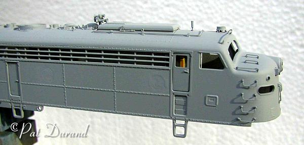
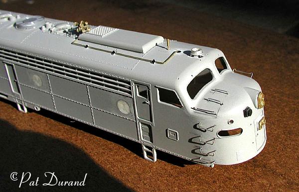
Plug round port hole side windows and headlight openings with .20 styrene. You can get close sized plugs by using a paper hole punch to cut the .20 styrene. Glue these in place with ACC as you will find common plastic solvents will not work on the locomotive body. Several light applications of the testors countour putty, with light sanding between will close the openings. Do not overdo this procedure. On the prototype you could clearly see the outline of the weldments where the windows were plugged.
After the headlight openings are closed use ACC to attach the brass or white metal Pyle style headlights. Pre drill the castings and after the acc cures continue these holes through the plastic plugs to reopen the light path. After all spray painting is done paint the interior of the lamp holes silver.
CAUTION: Once painting is done and glazing is installed, DO NOT USE ANY ACC on the car body as you risk damaging the glazing with fumes from the ACC. Any fingerprints you have left on the glazing will attract the fumes and appear on your formerly clear windows. So plan assembly that requires ACC before painting operations. Use a small paint brush and denatured alcohol to wash finger prints from windows.
Drill out the Marker lamps. These will get new fiber optic lenses later.
Remove the skirts at the bottom of the side outboard of the two fuel filler locations on each side. Cut near the bottom rivet line with a zona saw and then finish with a sharp file or knife.
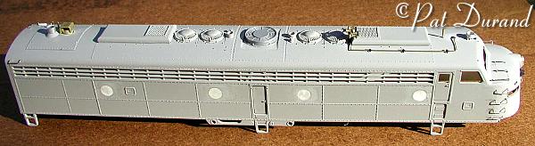
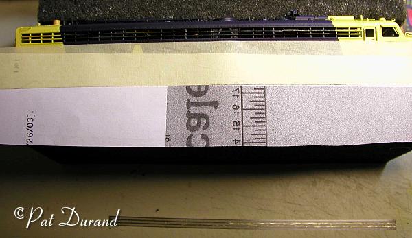
Installing the 48" flat top Dynamic fan is a little tricky (see overhead view). A flat recess must be made in the center of the roof by first making two parallel Zona saw cuts scale 54" apart centered across the top of the carbody. At the roof centerline this cut will be about 1/16" deep tapering out to 0 with the radius of the roof. These cuts should not penetrate through the car body. The material between the two cuts is then removed with sharp flat files to create a flat recess for the fan to set into. Easy does it.
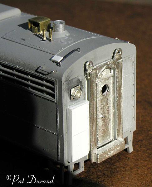
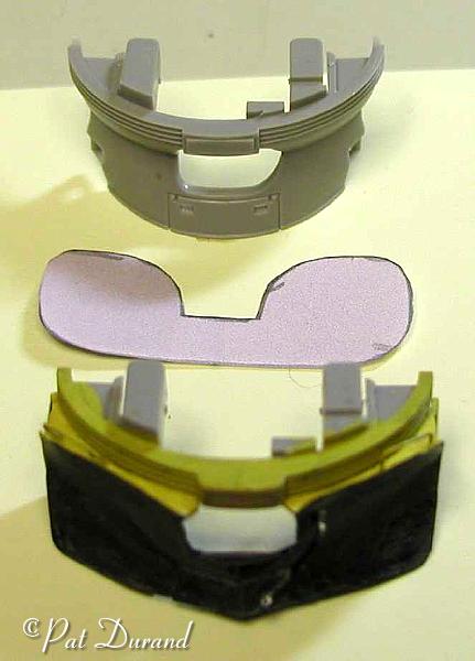
The rear wall of #2401 requires a total rebuild. Remove the door and the diaphragm, they will just snap out. The stiffener ribs pressed into the sheet metal on each side of the rear door on most F and E units do not exist on #2401. Remove these from the casting with a sharp chisel blade and finish with a light sanding. To install the Details West rear door and vestibule you will need to build new collision posts for it to set on. A strip of .40 styrene a scale 9" wide should be glued on edge to the back of the door casting, flush with the inside edge of the diaphragm frame. Another piece can then be added across the top. The assembly is added to the rear wall over the original door opening. Use ACC to tack this in place and then finish the job by filling the void between the casting and the plastic wall with mixed JB Kwik Weld. The back up light casting included with the door kit, should be centered in the panel to the left of the door and inline with the bottom edge of the side radiator opening. The control box is made up of two layers of .40 styrene cut to scale size 26"X 62". The details of doors are simulated with sharp scribe lines made with a #11 blade. Chase all the holes for the grab irons with a sharp drill prior to adding the grabs.
Steam generator vents and stacks are non standard. These are simulated with thin wall brass or aluminum tube. The original exhaust is drilled out to fit the new stack that extends about 10" above the roof. The intake air is protected under a cover which is just an inverted channel supported over the tube. With dissimilar materials this is a place for ACC again. There are two vertical pipe vents to the left of the exhaust. There are no good roof photos of these so punt as to the location referring to prototype photos as always.
Now that the heavy modifications are done, the details can be added starting with grab irons. To avoid extra masking effort, do not install vertical grab irons that will span the line between blue and yellow paint. These can be painted yellow and added after masking and spray painting. There are grab irons on the roof side edge near the rear corner. A single long grab iron of irregular shape is installed at the left corner of the roof parallel to the rear wall.
Detail Associates includes a strip of plastic rivet heads with many of their grab iron sets. These add a lot of interest if you take the time to install them. I find it is best to position the grab irons first and secure them with ACC from the back side. Let them cure overnight and then add the rivet heads. To drill the hole for the rivet accurately here is a trick. "Center punch" the hole location right next to the leg of the grab iron using the end of a dental pick to press a depression in the plastic. Now the drill will not wonder around when you drill the hole next to the leg of the grab iron.
A ladder grab iron is added on each side of the nose. You ask what are "ladder" grab irons? Prior to the FRA mandating a full set of grab irons up the nose for access to the windshield, the window washer would lean a ladder up to the ladder grabs. Those bumps kept the ladder from slipping sideways on the nose. Make sure to secure the grab irons from the inside with ACC. The next day cut the excess legs flush with the inside of the car body to avoid interference between the dash board and body.
Add the Firecracker Antenna, and rotary beacon. Drill a close fit hole for the beacon lens to pass through the roof. Use this hole to position the beacon base and glue it with thin ACC. Do not install the lens at this time unless you plan to mask it for painting.
From photos the five chime Nathan horn is positioned between the forward winterization hatch and the first open fan. The air line is routed forward to the original air horn position on top of the roof. You can simulate fittings with a small drop of ACC on the wire before installation. The brackets for support of the air line are just small bits of styrene angle iron. Assume the use of ACC for all dissimilar materials unless advised otherwise.
The ARR modified most radiator fill caps by welding a bar handle across the top of the pipe cap. Just ACC short stubs from the grab irons across the top of the caps which are located next to the exhaust stacks.
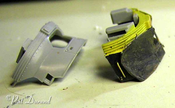
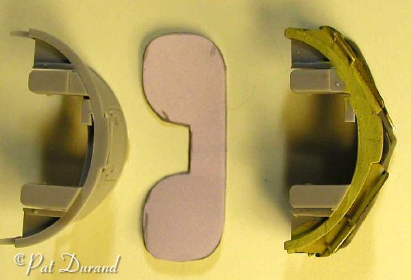
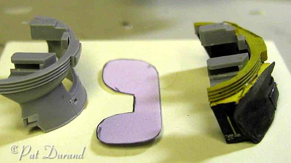
The snow plow pilot is fabricated using the stock pilot as a base. Use a large 3/8" tapered round file to remove material from the face on each side of the stock pilot. Create a depression from just below the ainticlimer at the outside edge running down to the point of the plow. Do not break through, just make a curved depression to receive the new plow to be fabricated from .10 styrene. You can find a template and instructions for forming the plow face on John's Alaska Railroad Pages under Modeling. In short, two pieces of .10 styrene are shaped and formed using Tenex solvent cement to change the surface tension of the styrene. These two pieces are then tacked to the face of the pilot with ACC. Voids between the plow and pilot are then filled with JB KWIK Weld. Allow the assembly to cure overnight and then fit and add .20 styrene spacers just below the anticlimber bolts and the rear of the plow. The side brace is then added from the spacer down behind the edge of the plow wings. Finish shaping the plow with files and a sharp blade. The hand grabs are actually installed into the spacers behind the plow but appears to be welded into the plow. Use paper or .05 styrene to form the doors at the point of the plow. These doors provide two functions. If the locomotive is used in train (not the lead unit) the doors are open to get access to the steam heat line which passes through the opening. The doors can also be opened to gain clearance when on rare occasions this plow was coupled face to face with another plow. The final step is the single train air brake hose with glad hand mounted to the left of the coupler. Remove the angle cock handle at the top of the hose. The angle cock was moved behind the left corner of the plow to avoid it being turned on or off by compacted snow. For similar reason the coupler cut lever was placed on the right side just behind the plow flange.
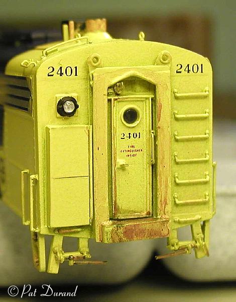
Painting required a light gray primer to blend new parts with the original kit so the Yellow will cover properly. Let it cure overnight before spraying both ends with CNW yellow and allow another day for cure before masking. Tips on masking can be found on John's Alaska RR Page under modeling. I use Scotch Magic Mending Tape with about 1/8 inch strip exposed over the edge of paper backing. Use several small pieces of paper with tape attached so that each strait line is masked with one piece. At the junction of lines tape over the joints and fold the paper to encapsulate areas to be protected from over spray. Remove the masking about 30 minutes after the final spray so the paint can heal along the masked edge. To mask irregular shapes such as the ARR round logo on the side of the locomotive, use a compass to draw a circle on a self adhesive printer label, cut it out and apply it as a mask.
The Microscale 87-480 decal set has special 9" high numbers for the nose, and 60" high A for the side for the 2401 and 2402. A proper placement diagram is included. I trim decals very close, apply them with "wet" water and after they settle down apply Microscale Solvo Set with the glass stopper rod. Allow the decal to dry thoroughly in place and make another application of Solvo Set where ever there are voids under the decal. When cured over night an application of a flat dull coat spray will fix them in place. If you want a slightly gloss finish use Model Masters Semi Gloss Clear coat. I never use high gloss unless i want to simulate running in a rain storm.
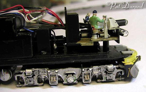
Do Not spray paint the trucks. Much better and cleaner results are achieved with a near dry brush applying aluminum paint by stabbing into recesses and finishing with a few vertical strokes. Weather lines then will appear as vertical. Small dabs of rust on the brake shoes and a thin wash on the springs will add character. Little dabs of pea green on the wear plates next to the journal will prove this is a modern '80s unit with high density "plastic" wear plates. This dry brushing results in no fuss and no paint on the pickup wipers or the wheel contact surfaces. The speed recorder goes on the second journal on the right side. Drill the center of the journal out to allow the post on the recorder to slide in. Use a small amount of Goo applied inside the hole and on the recorder pin and press them together. After about 2O minutes apply a ring of ACC around this joint and now we have the best joint we can make between the engineering plastic side frame and the recorder. Just bend the "cable" in an arc upward and cut it off short of the frame so there is no interference. This ends up behind the step and no one will ever notice it is not connected.
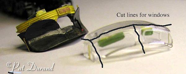
Now we are getting close with the next steps adding glazing, headlight lenses (fiber optics) and a backup light lens. While we have been adding details near the window openings we have changed the clearance of these openings ever so slightly. The Windshield and side windows are one clear plastic casting. Save yourself some grief and turn this into four pieces by cutting the side window sections free. Then trim excess plastic back with a sharp #11 blade to make clearance. The front windshields should be installed independently. Fix all glazing in place with Super Crystal Clear. Sun shades can be made from .10 styrene or paper and glued to the overhead above the windows with Crystal Clear. Look at photos to determine proper position and only install those shades that you want in the deployed position. Over each window there are two shades. One large shade covers 2/3 of the distance from the outside toward the middle. A smaller shade covers the remaining area to the center post. On the center post there are vertical shades mounted on each side. The wing windows and main side window can be enhanced by adding a piece of wire to simulate the frame between the two. Use Super Crystal Clear and paint a small amount into the recess between the windows. Drop the cut wire into the Crystal Clear and remove the excess glue with a dry paint brush.
Number board digits on the prototype are individual cutout panels that can be changed in a bracket holder to reflect either a train number or locomotive number. #2401 and 2402 were both used as lead units on the Anchorage-Fairbanks express passenger trains in the summer. North bound they would display the single digit 1 in the center position of a 5 panel bracket. South bound this was train 2. The bracket was accessible from inside the nose of the locomotive and fortunately on this model you can mount your numbers the same way. After the glazing is in place, cut your number and insert it on the back side of the glazing in reverse order. There is no adhesive on the water slide decal so they can be installed either way and secured with Solvoset or Microscale Super Crystal Clear in this case. Use flat black paint and vertical strokes to paint out the void spaces on the inside of the number board, If the numbers are slightly crooked and a little light shines through around the edges, great! That's what the real one looked like at night.
Use scale 4" diameter fiber optic material for the headlights. About a two inch piece will do you. Light a candle and then approach the side of the flame with the end of your fiber optic rod. You can make several lenses before you get some that are consistent in size. You will soon get the hang of making a bulbous lens on the end of the rod. Cut the rod off at the proper length to get into proximity of the light source. Insert the lens through the lamp holes and secure from the back side with Super Crystal Clear.
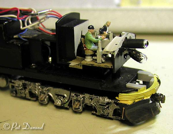
I added a two person locomotive crew. The engineer is a heavy set guy about 60 and the fireperson is a small gray haired woman of about 45. On passenger trains we still had a three man crew with the Conductor out back. The original crew members looked like "Little People" from a Kansas tornado story and they got lost! To position the crew, remember they set high in the cab and look down at the world. In order to see out the front of an E or F unit your eyes must be on level with the top of the side windows. The seats can be moved back or it is easier to carve off the legs and back of your crew so they set in the proper position is the cab.
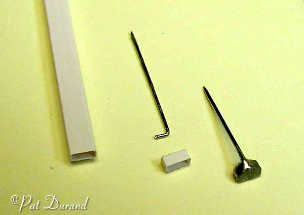
These locos had electronic bells mounted on the cab roof. No commercial part is available that I know of. So use a piece of Super Styrene Rectangular Tube .08 X .56 box section. With a new #11 blade reach into the end of the box section and taper the inside of the four walls to thin them at the outside edge. Now part off about 3/32" of the shaped box section. Cut the end of off a strait pin and put a 90 degree bend in one end leaving a 1/6 stub. Center this stub in the box section from the back side and fix it in place with ACC while grasping the other end of the strait pin for a handle. This is a good place to use accelerator. When cured, carve and file the back side and fill any remaining voids, paint and repeat this process until you have a nice finish. By now you should have a feel for this piece of artwork and soon you will be holding an electronic bell with a long handle attached. Cut the handle off about 1/8" below the bell, drill a hole in the cab roof and install the unit with ACC.
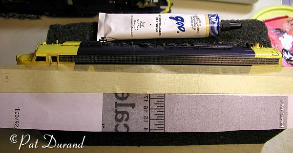
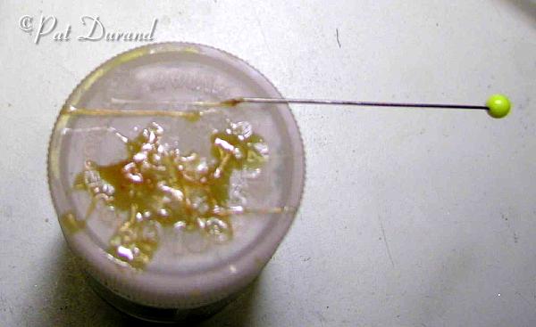
Installing the stainless steel FARR grills intimidates many people. Here is an ideal job for the Walther's Goo. Most ACC will be brittle and will not take the expansion and contraction of this long metal piece attached to plastic, popping off or buckling. Making a clean installation with out adhesives getting all over is a concern. GOO is the answer. Start by supporting the locomotive on a piece of foam or a folded towel (see diagram). Take a sheet of typing paper, fold it in half and add a strip of masking tape along one long edge with about 1/4" of tape exposed. Lay this mask along the side of the loco and secure the tape along the bottom edge of the grill opening to protect you paint job. Now put a dab of Goo on a scrap and prepare to transfer the GOO in small amounts to the tip of a straight pin. You will discover the curse and blessing of GOO when small tendrils of rubber string follow the pin. Perfect! Now just learn to control the strings by dabbing the tip of the pin onto the two center ribs of the grill opening and depositing a thin layer of GOO the length of the ribs. DO NOT ATTEMPT TO PUT ADHESIVE AROUND THE PERIMETER OF THE GRILL OPENING! IT AIN'T NEEDED THERE. It takes very little GOO since this is a true contact cement. Now repeat the process on the two center ribs on the back side of the Farr stainless grill etching (see diagram). As the GOO begins to cure, use tweezers to pull of any oversize globs while taking advantage of any strings that appear by bringing them back to the working surface. After about 3 minutes you can press the two glued surfaces together to make contact. Align the grill carefully, and make any adjustments immediately. After about 15 minutes the grill is an integral part of the body and any attempt to remove it will result in damage to the grill and or loss of paint from the model. You can remove the mask now and enjoy the result. If you find any excess glue has come to the surface between the grill bars. LEAVE IT ALONE until tomorrow when you can flick it off with a sharp #11 blade.
Some highlights can be painted to enhance the model. At various times during the locomotive's life these items would have been painted and then weathered away. Paint bright red, fuel filler caps, emergency fuel cutoff, air safety release on air tanks. Touch of aluminum paint on glad hands, radiator fill caps, wear points on steps, plow and rear door deck to be followed by rust wash.
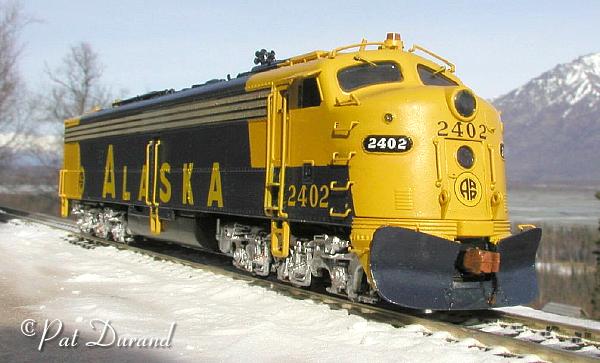
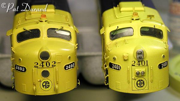
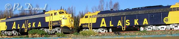
While #2401 and #2402 share a paint job many of the details are different as shown. #2402 has extra grab irons on the cab roof, fewer grab irons on the nose, MU connection is in a hatch to the left of the headlight instead of exposed to the right, and prominent lift rings on the front of the frame.
Robert Garner, came through with a photo of the rear wall of Wisconsin Southern 10C formerly Alaska Railroad 2402 and it has the same configuration as 2401. One adaptation that they added to #2402, their 10C, is a closed circuit television system. From the coaches in the train you can get a forward view from the locomotive cab. A two inch black hole to the left side of top headlight houses the color camera. Here we have the prototype imitating the hobby.
Enjoy the greatest hobby in the world.
Materials list for Alaska Railroad E8 #2401 and #2402 by Pat
Durand
Adhesives
Insta Cure Super Thin ACC
IC-2000 ACC with rubber
Walthers Goo
JB KWIK Weld
Testors Contour Putty
Ambroid Plastic Weld
Tenex Plastic Weld
Super Crystal Clear Window adhesive
Microscale decal set 87-480
Scale Coat II B&O Royal Blue
Scale Coat II CNW Yellow
Following parts were used in construction of ARR#2401
Details West:
AH-187 Nathan M5 5 Chime horn $2.95
RA-157 Firecracker Antenna $1.95
RB-106 Flasher Beacon $1.00
FA-208 Rear Door Details $5.50
HL-148 Pyle GyraLight (upper light)
SR 284 Speed Recorder $1.95
Details Associates
DA-101004 Pyle 2 lite early (lower light)
FA-2003 48" Flat Top Dynamic fan $2.25
Sy-2202 17" Drop Grab Irons
Sy-2215 Ladder Grab Irons
Kadee #58 scale couplers. Use the factory retainers with coupler and flat spring in rear mount. Do not use spring in front mount.
Single trainline air hose for front end pilot, brass is best.
Materials:
.10 styrene approx. 2"X2" piece for snow plow
.20 Styrene approx. 2"X2" piece
.40 Styrene approx. 2"X2" to build the control box at left rear
corner.
Scale 8" Square styrene about 1/2" to make base for nose MU Connector.
Scale 1" Wire for Air horn line and coupler lift bar approx. 2.5"
long
Aluminum or Brass tube 2 pieces .25" long for Steam Generator vents
Scale 4" Fiber optic for markers and headlight lens 1 piece 2" long
Rectangular Tube .08 X .56 inch #521-51 1" long piece for bell. by Raboesch
Super Styrene Midwest Products Co.
Model photos
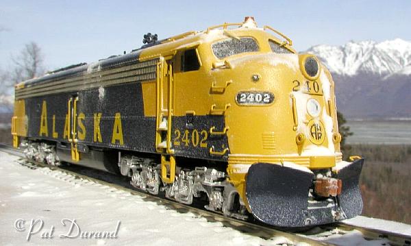
2402 after fresh snow
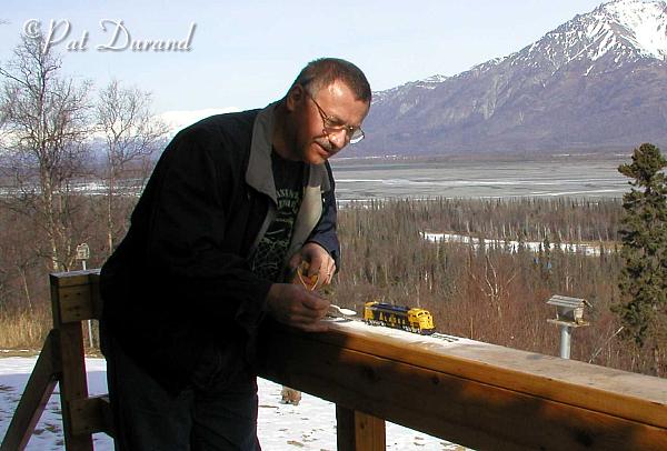
Pat Durand making snow
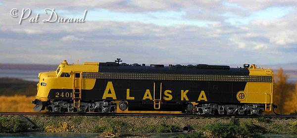
2401 in fall
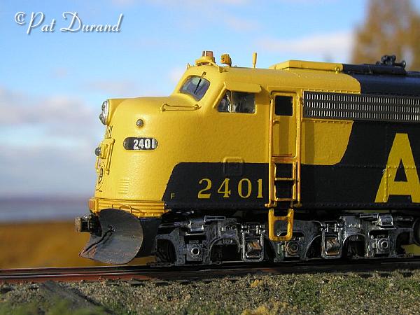
2401 close up
2401 and 2402 meet at Carlo