Erection of Hurricane Gulch Arch Bridge on Alaska Government
Railway
Railway Review
May 6, 1922
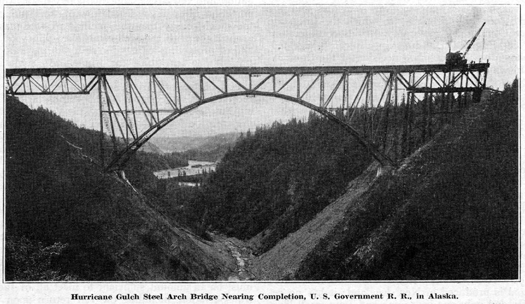
A steel arch bridge, 300 ft. high, has been completed over the Hurricane Gulch on the United States Government R. R. in Alaska. This gulch is 284 miles north of Seward and well on the way toward the Matanuska coal fields that are to be connected with tidewater.
The span of the arch is 384 ft. and nearly 1,000 tons of steel went into the arch proper, besides 530 tons in addition that were required to construct the approaches. The bridge structure is 914 feet long, with deck spans 120 ft. long at either end of the arch. At the south end there is a plate girder span 50 ft. long, while at the north end there is a steel viaduct 240 ft. long.
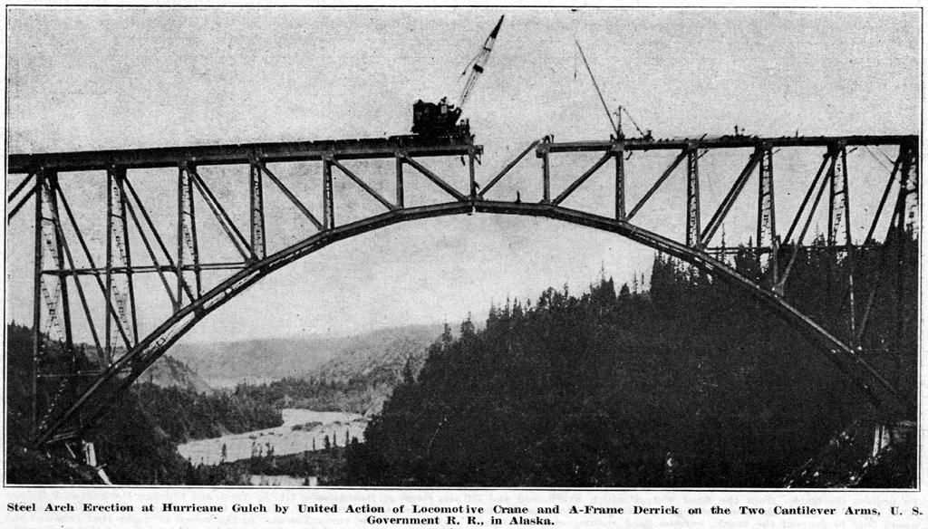
When the engineers planned on the construction of this bridge they determined that if the bridge was to he built by the cantilever method it would be necessary for each half of it to be built out from the shore and held back by steel backstays. It was clear that it would not be a difficult job to erect the south half of the arch, for the track of this new railway ran right up to the south edge of the gulch. There a construction yard could be established, as was afterwards done. The real trouble would come when it was necessary to transport the construction materials across to the far side of the gulch. To move these materials around by some overland route was found to be impracticable. For a time cableway transfer was favorably considered, but it seemed not adapted for handling the heavy members. The method finally decided upon was to lower the members to the bottom of the gulch by means of a locomotive crane stationed on the outer end of the south half of the arch. On the north side an A frame derrick was set up, and the load falls from this derrick were lowered to the bottom of the gulch and hitched to the member. Then both sets of falls, on the derrick and the crane, were taken up simultaneously. In this way the member was brought up the slope until it was just beneath the position that it was designed to occupy. Then the locomotive falls were released and the derrick lifted the member up to place. Between the erecting units there was a maximum gap of 192 feet. However, this method did not put on either boom any more strain than when either boom had to carry the entire load vertically.
As far as possible, the material was riveted at the yard. In the case of each bottom chord member the center of gravity had been figured out carefully in the drawing room. Then when the hitches were made they were applied at such points that the chords would hang in practically their permanent position while they were being placed.
Careful attention was given to the problem of getting the shoes of the arch set the correct distance apart. For this purpose a 500 ft. steel tape was used, and, of course, corrected for temperature. It was marked to measure the distance of 384 ft. the bridge span, while it was supported at the zero and 384 ft. marks under a 50-pound tension. The real test came when the two halves of the arch were lowered to position, but they went together to an accurate fit.
Backstay bars connected the anchorages to the 120 ft. approach spans. These were telescopic in action. Two pairs of backstay bars were provided at each anchorage. A 500 ton hydraulic jack was inserted in the telescopic joint of each pair. During the course of erection the two halves of the arch were slightly elevated at the middle of the structure. Steel shims in the telescopic joints held them in this position.
At the proper time pressure was applied to the hydraulic jacks, the shims were loosened and withdrawn, and then the halves of the arch were lowered to a bearing on a pin in each bottom chord, at the center.
Photos accompanying the article: