December 6, 2018
|
|
 |
In an effort to get the basic layout (minus switches) up and running by Christmas the team decides to have meals they can eat in the train room while working. Terry and John cook homemade pizza and Mike brought Zingers for dessert. Mike has nostalgic memories regarding Zingers and the crew dreamed of trying one. Well, tonight was the night. Mmmm! |
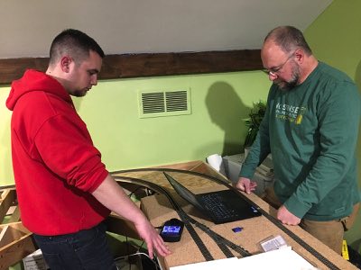
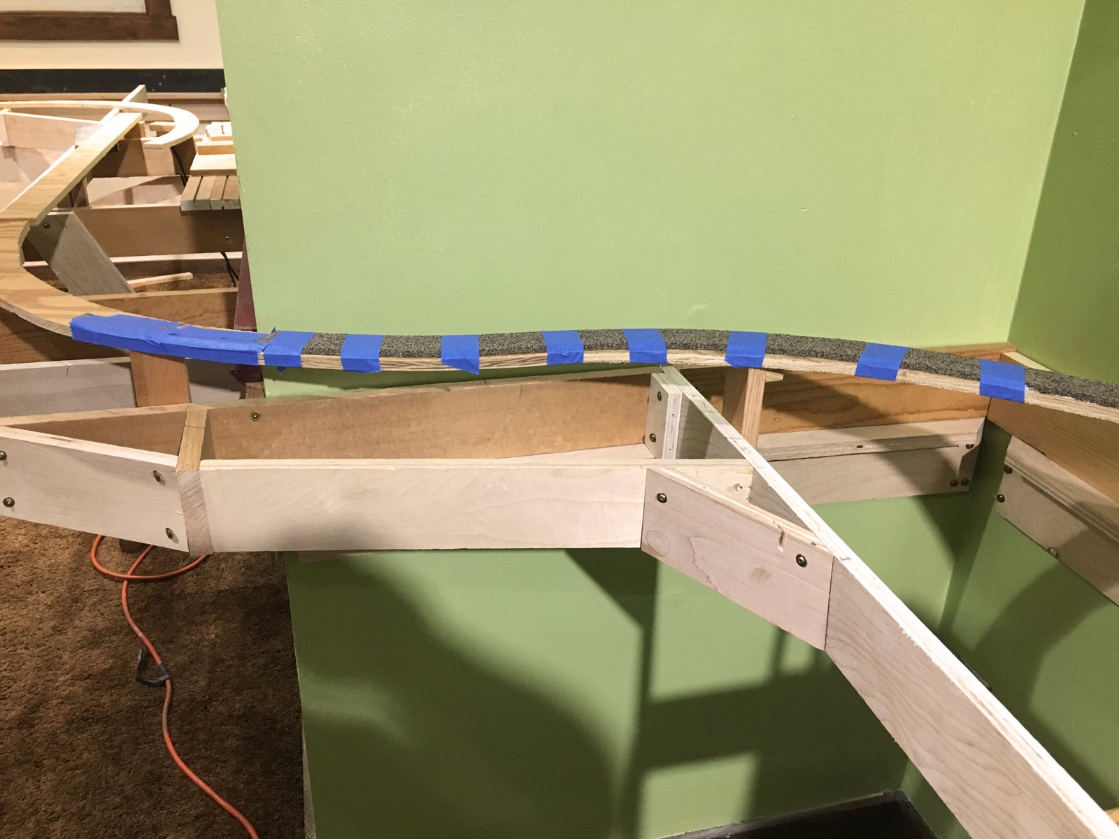
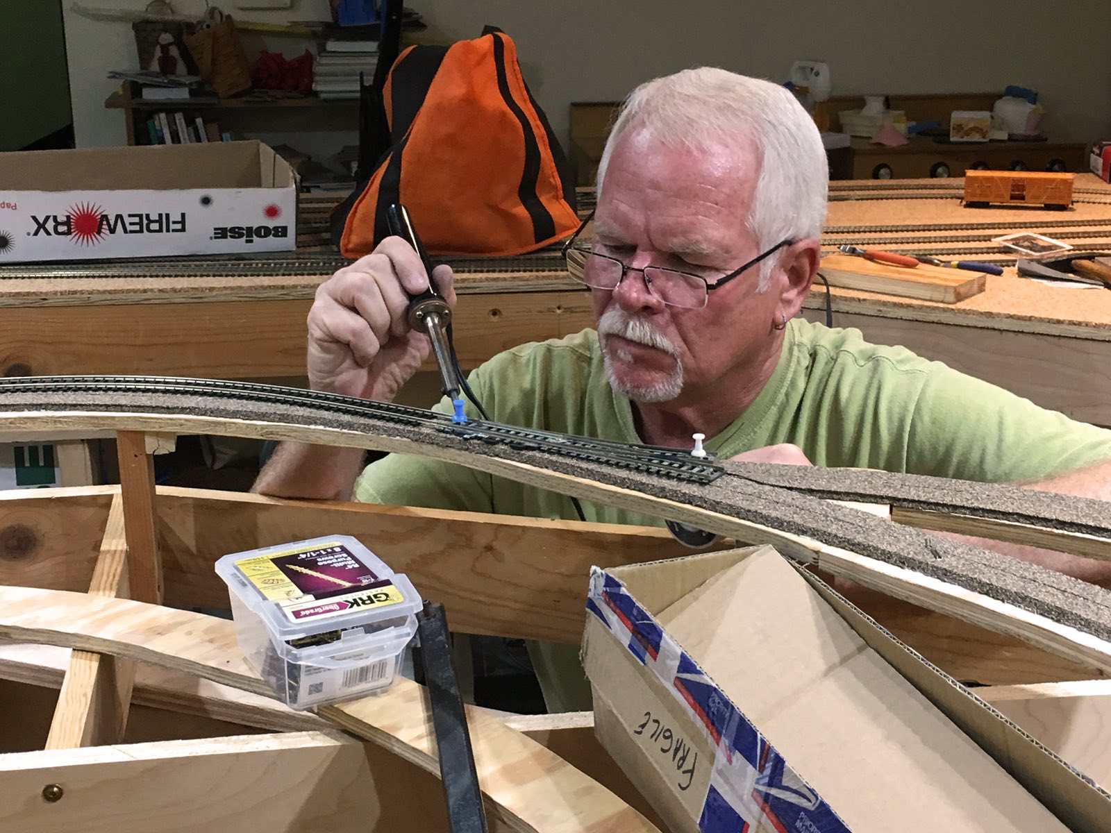
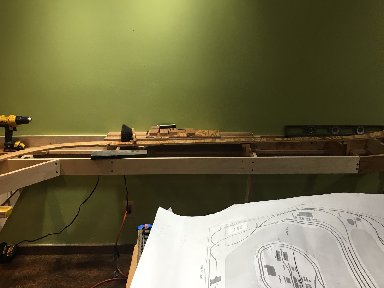
Tom, Zeus and Mike discuss the details of laying cork and track across the swing gate. If the swing gate has too much side-to-side movement then the rails will not completely align and the train could derail. Mike inserts an additional block to aid stabilization. Tom feels this will be enough to allow the trains to run without issue. |
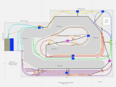
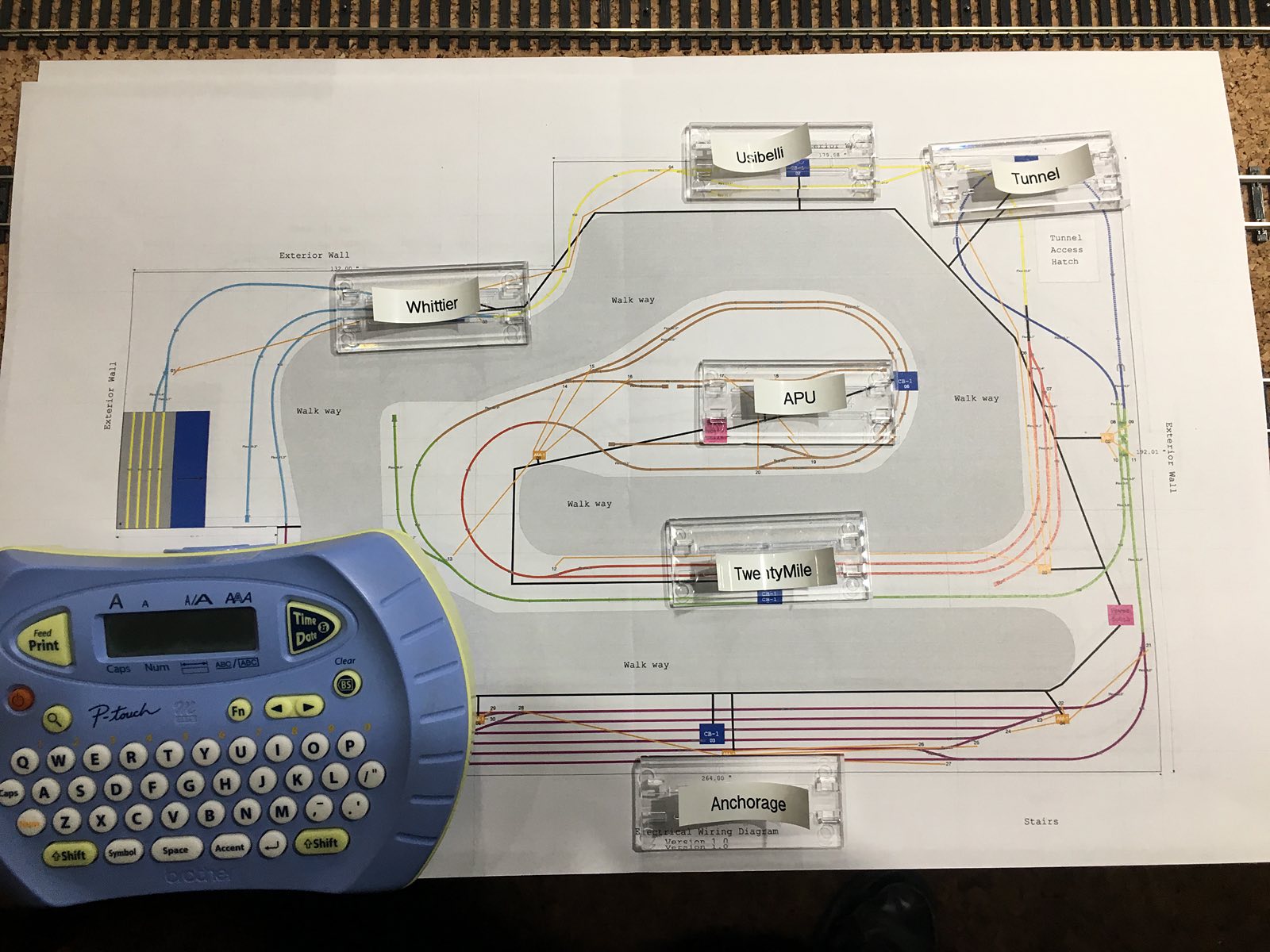
With carpentry construction about 95% complete our efforts turn to wiring. This drawing is an overview of RailPro product locations (CB-1s, AR-1 and AM-1s) as well as the wiring. The black line is the main power bus and corresponding routes to products. The orange line is wiring from the AM-1s to the Tortoise switch machines. Finally, each of the seven blocks is designated by a different color. For example, the Anchorage yard block is shown in purple while the Whittier block is shown in cyan. |
|
|
|
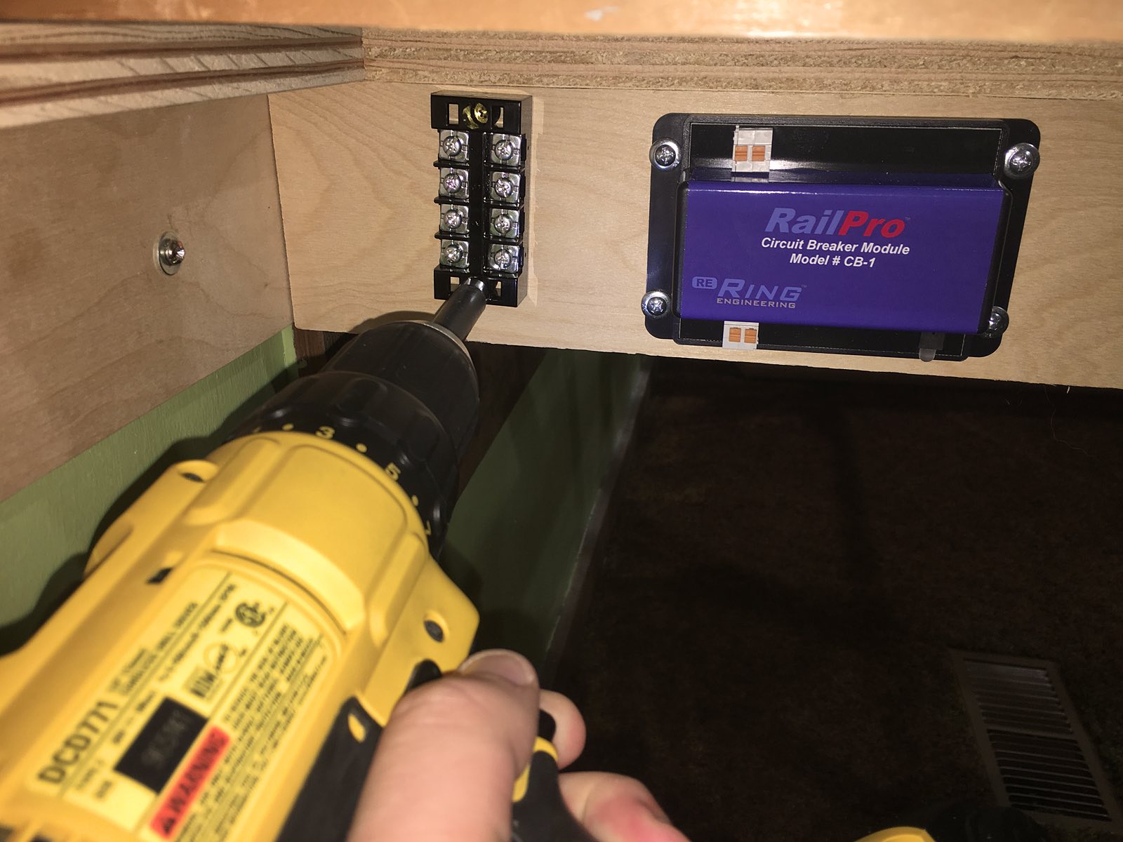
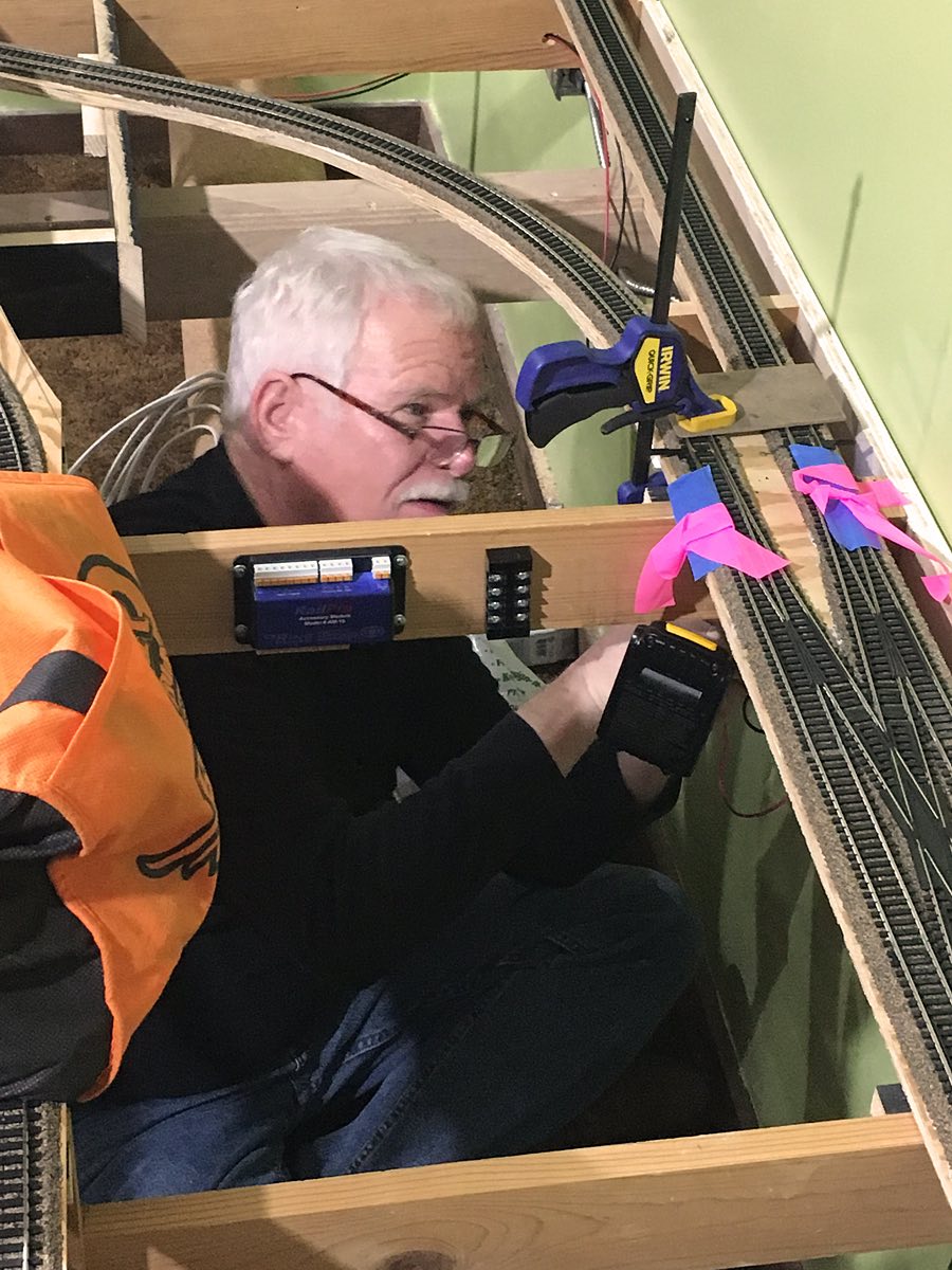
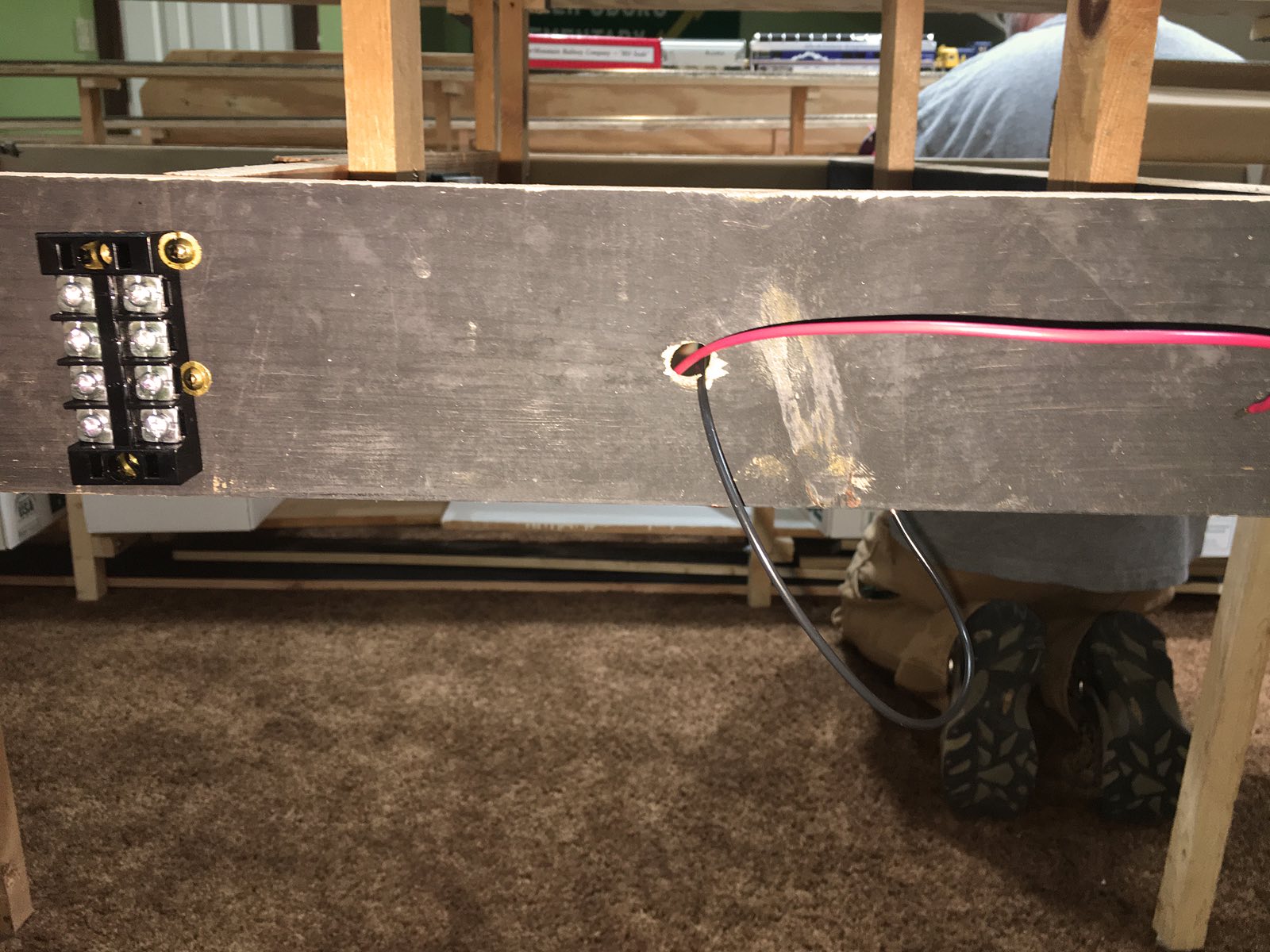
| Terminal blocks are used to route power from the main power bus to the CB-1s (Circuit Breaker/block), AR-1 (Reverse Loop) and AM-1s (Accessory Module/Tortoise control). These terminal blocks have see-thru plastic covers. These covers will prevent possible wandering toddlers from coming in contact with wires. John labels these covers with appropriate location names so electricians can easily understand what is going where. |
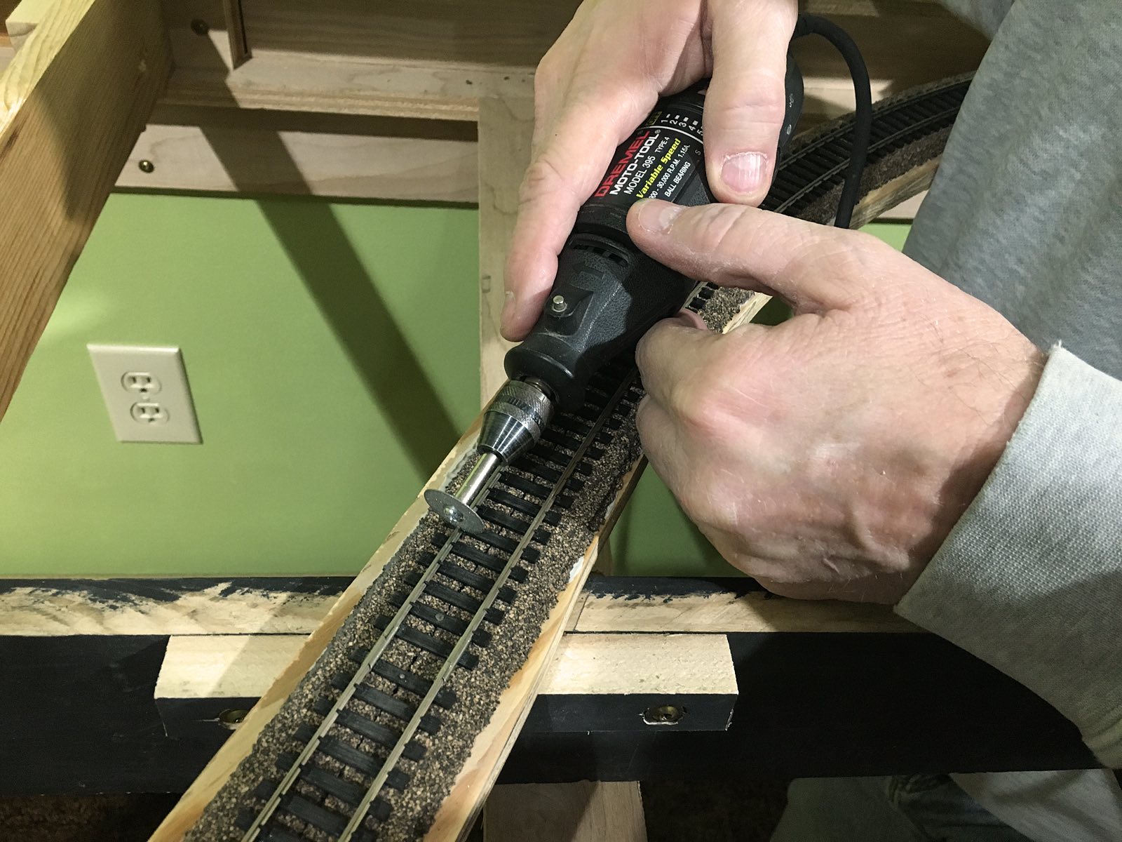
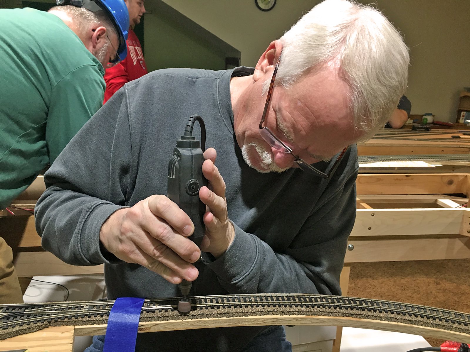
Blocks is the process of dividing the railroad into sections. For the RailPro system this helps to distribute power more evenly as well as narrow down the location of any possible short circuits. To create blocks Tom uses a Dremel to cut the gaps in each rail of the track. Next Thursday these gaps will be filled with Super Glue which will serve as an insulator as well as allow trains to pass over smoothly. |
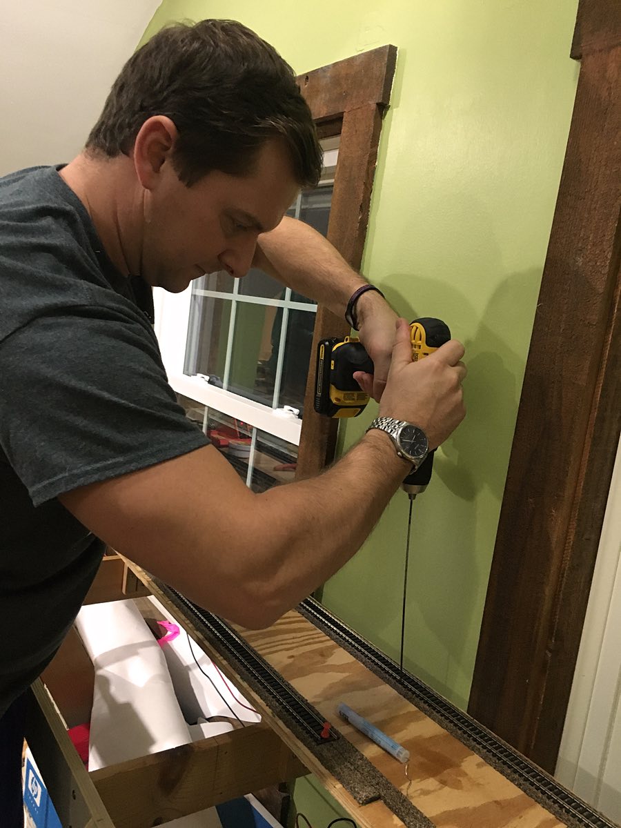
Drill Sergeant LJ mounts 12 terminal blocks throughout the layout. Each terminal block is located at a junction of the main power bus and a CB-1, AR-1 or AM-1. Mike and LJ also walk around the layout and drill the remaining holes through the L-girder cross pieces to accommodate the electrical wire runs. |
 |
|
 |
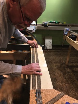
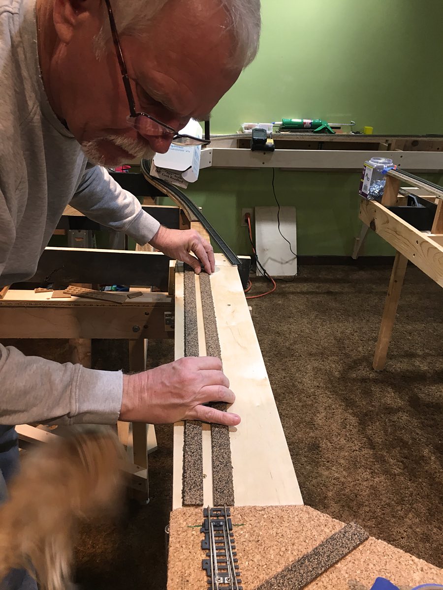
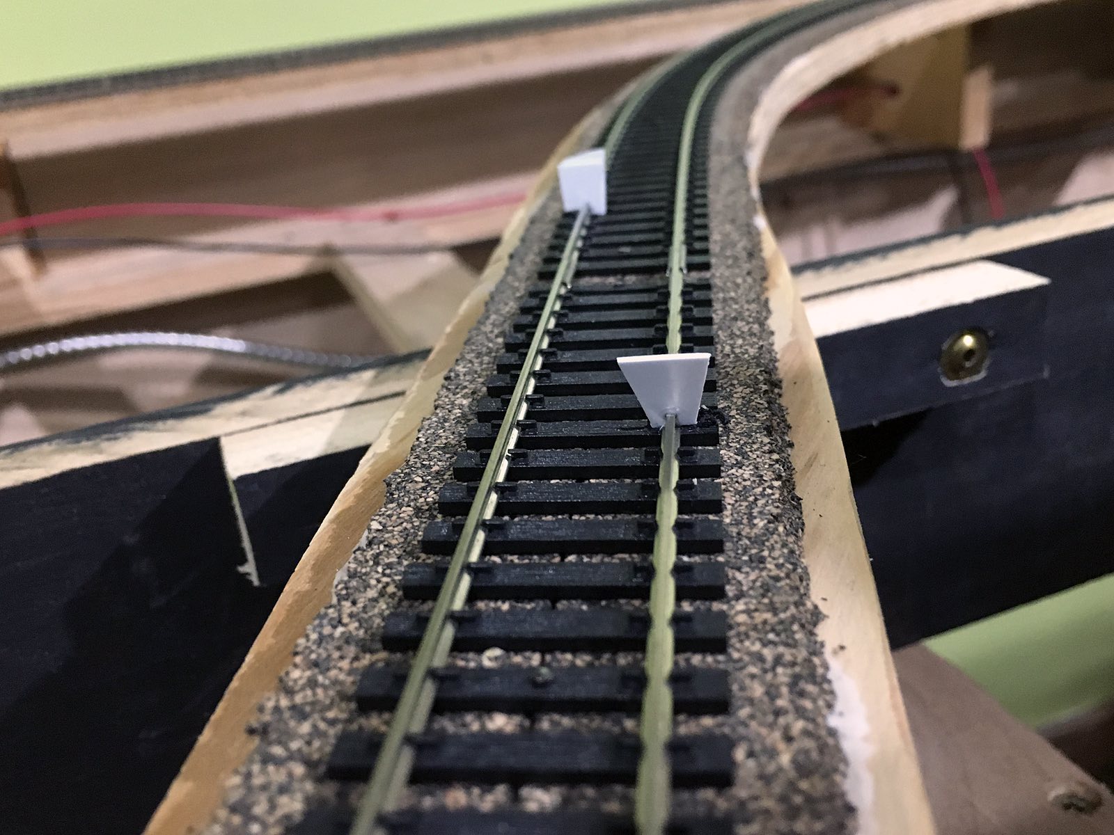
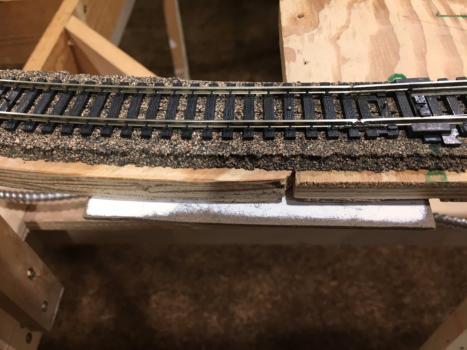
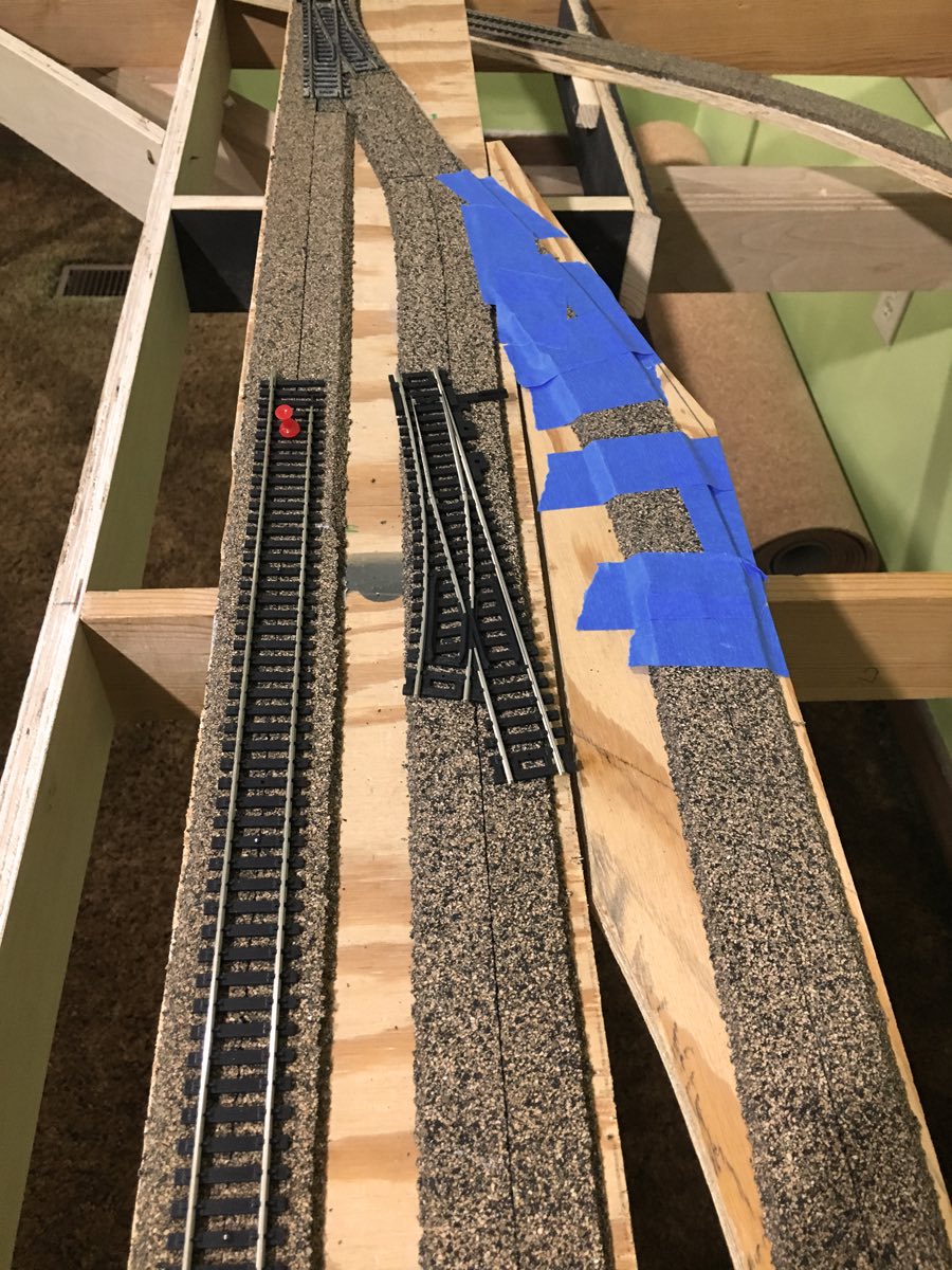
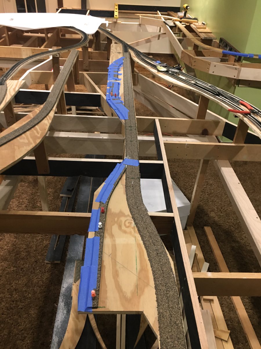
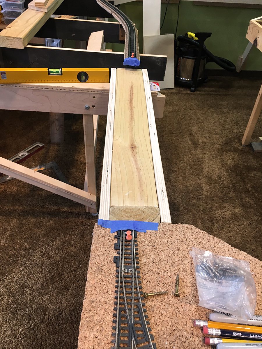
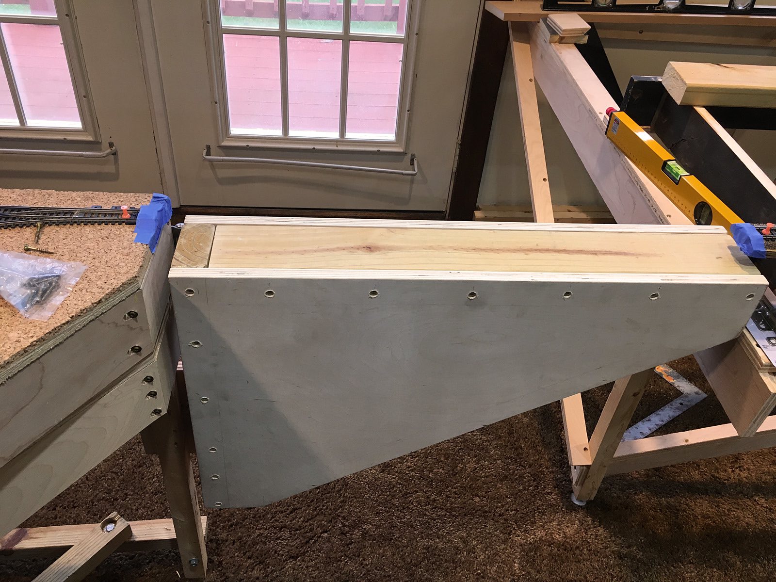
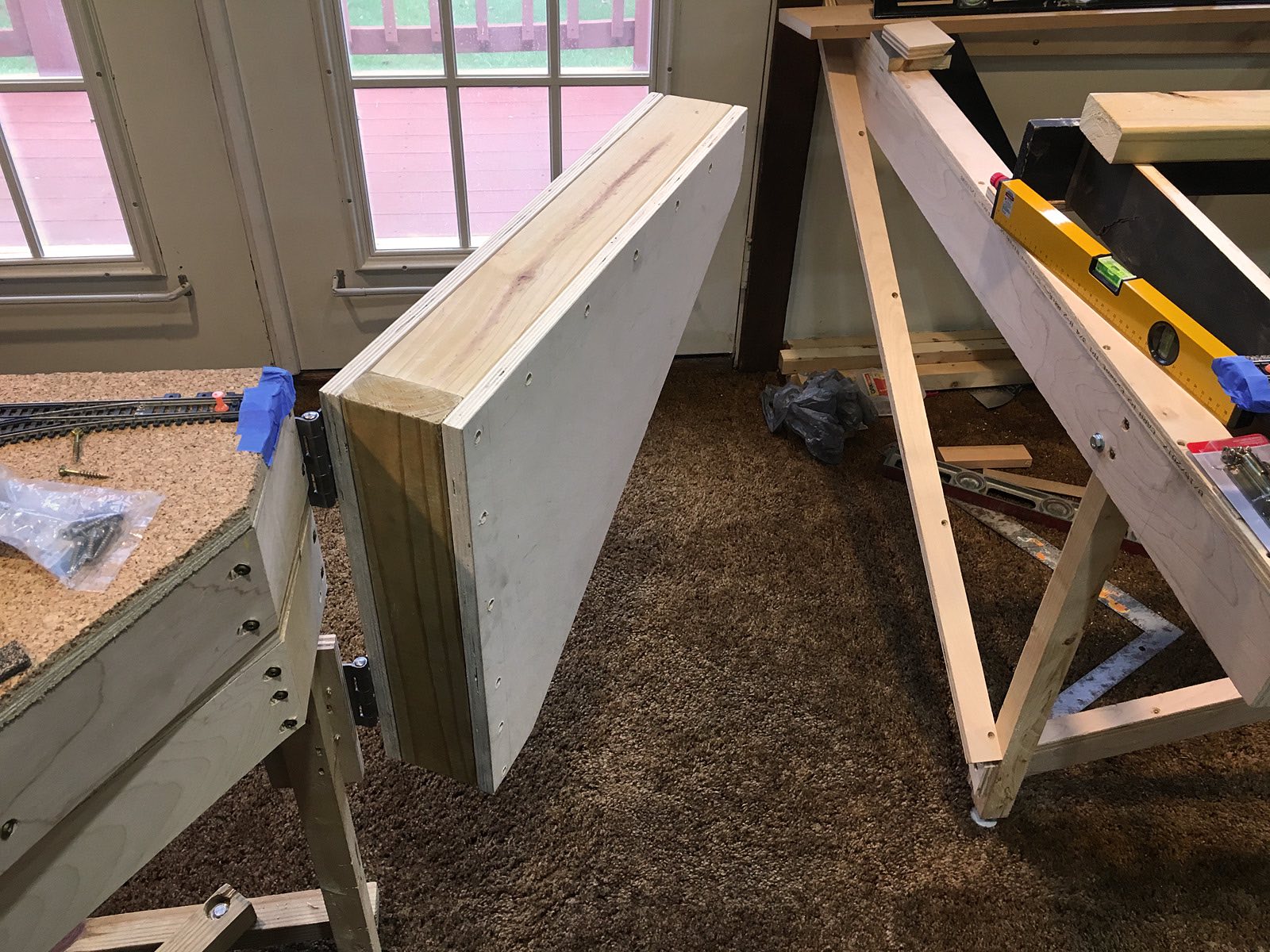
| Tom cuts the cork bed for the swing gate segment. The eastern (left) is cut at an angle to accommodate the swing angle of the gate. Tom then glues the cork bed in place. Finally, he cuts the track to the proper length and angle and sets it aside for next Thursday. |
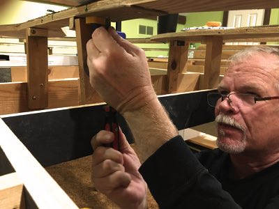
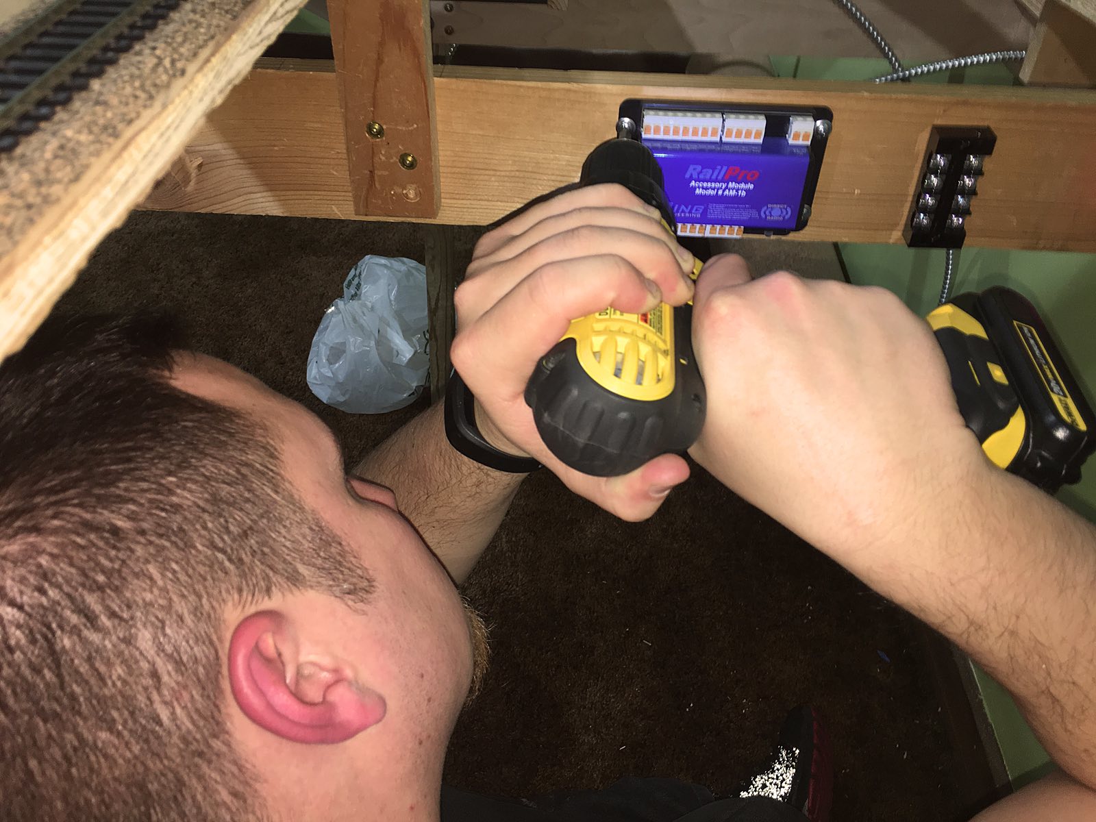
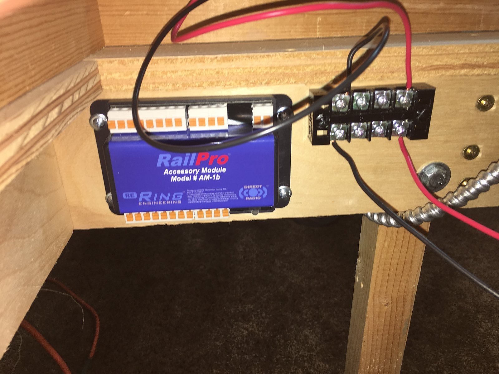
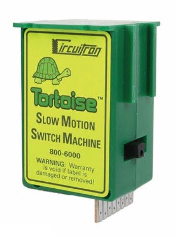
Doing various under-the-table contortions Drill Sergeant LJ mounts most of the AM-1s to the lower L-girder brace. This will allow plenty of access room for wires to run to the top and bottom of the module. The AM-1 is equipped with spring-loaded terminals for fast and secure connections that do not require a tool. |
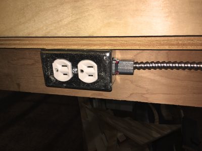
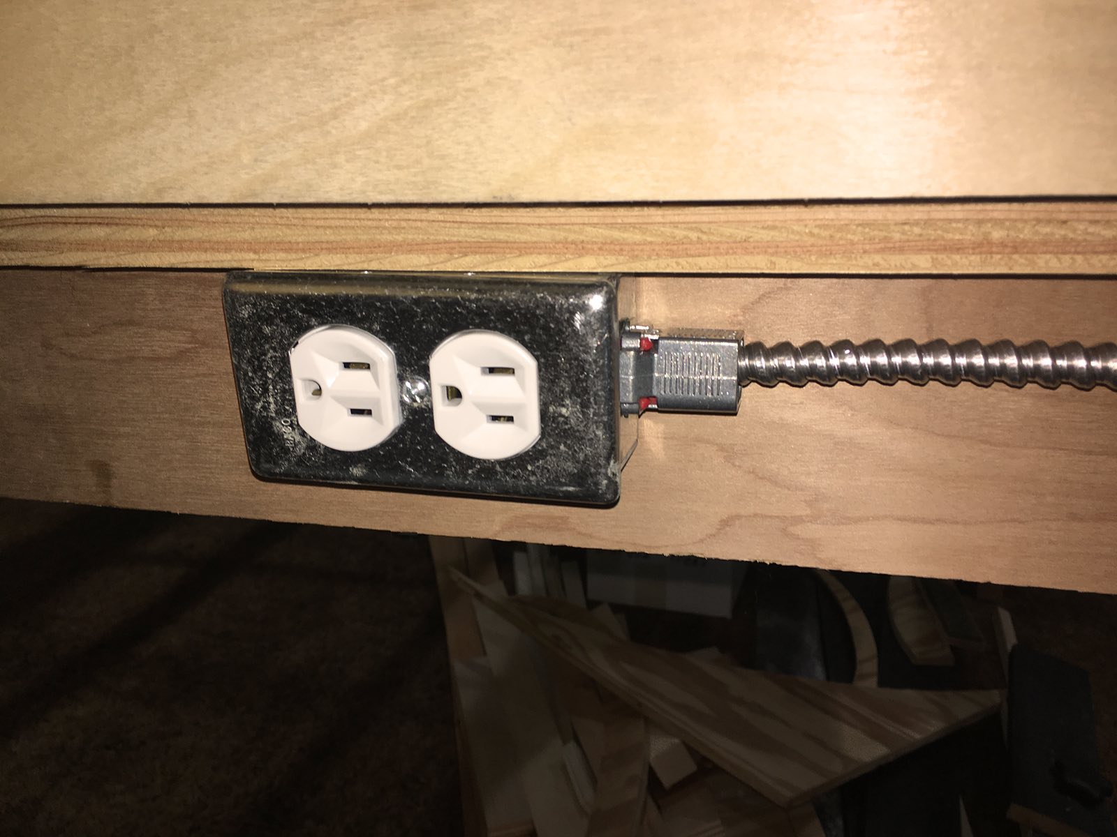
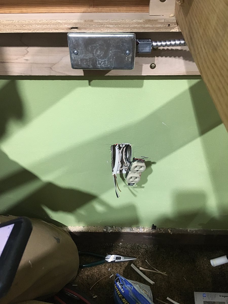
Mike installs an electrical outlet for the RailPro power supply at the APU. He then connects the corrugated conduit LJ ran two weeks ago. Next week Mike and LJ will connect the other end of this conduit to a new outlet box spliced into a wall outlet. Before finishing tonight, LJ and Mike locate the house circuit breaker for the wall outlet. |
December 13, 2018
|
|
 |
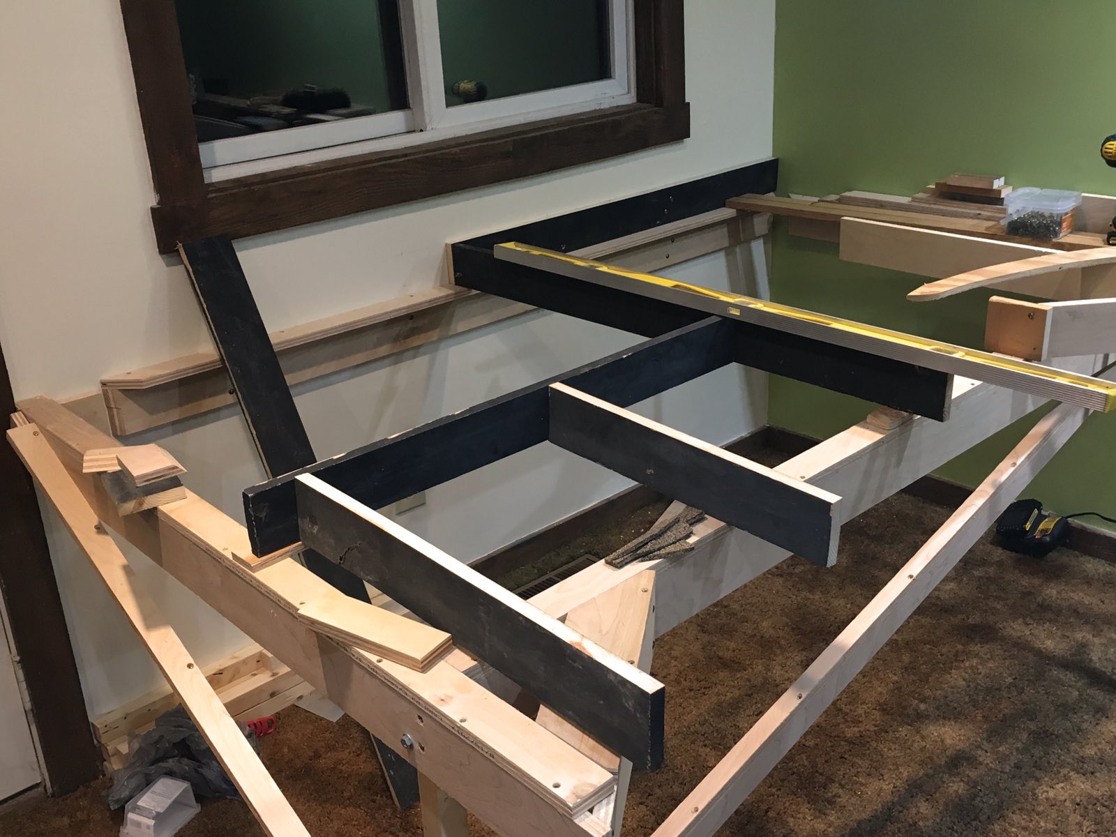
Metals plates were used underneath plywood road bed segments to join them together. This later proved to be a problem whenever snap switches were located directly above metal plates as Tortoises need a hole up through the base for the switch wire. Tonight Tom brought wood strips to replace the metal plates. |
Tom removes the metal plate and then puts the wood strip in place making sure to line up the holes for the Tortoise switch wire. Glue and screws are used to hold the wood strip in place. |
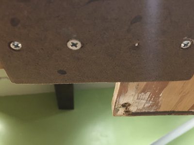
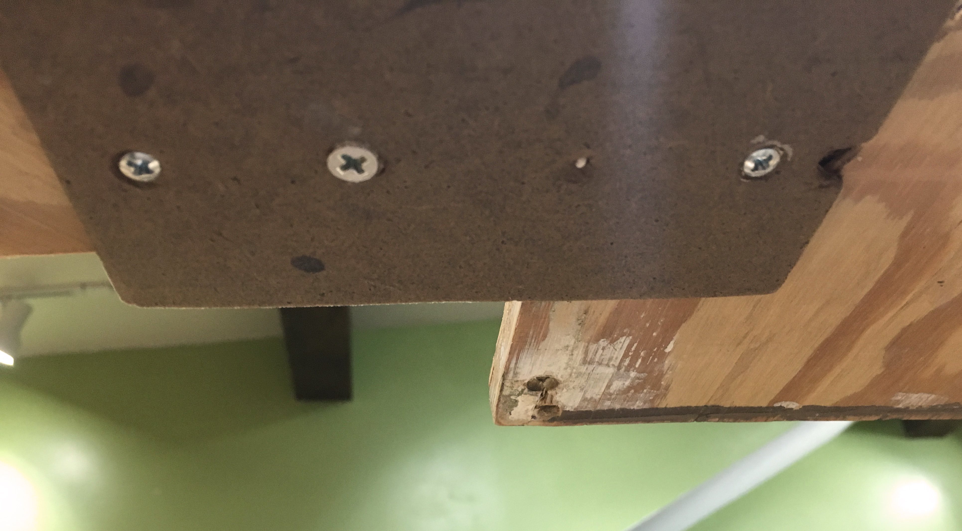
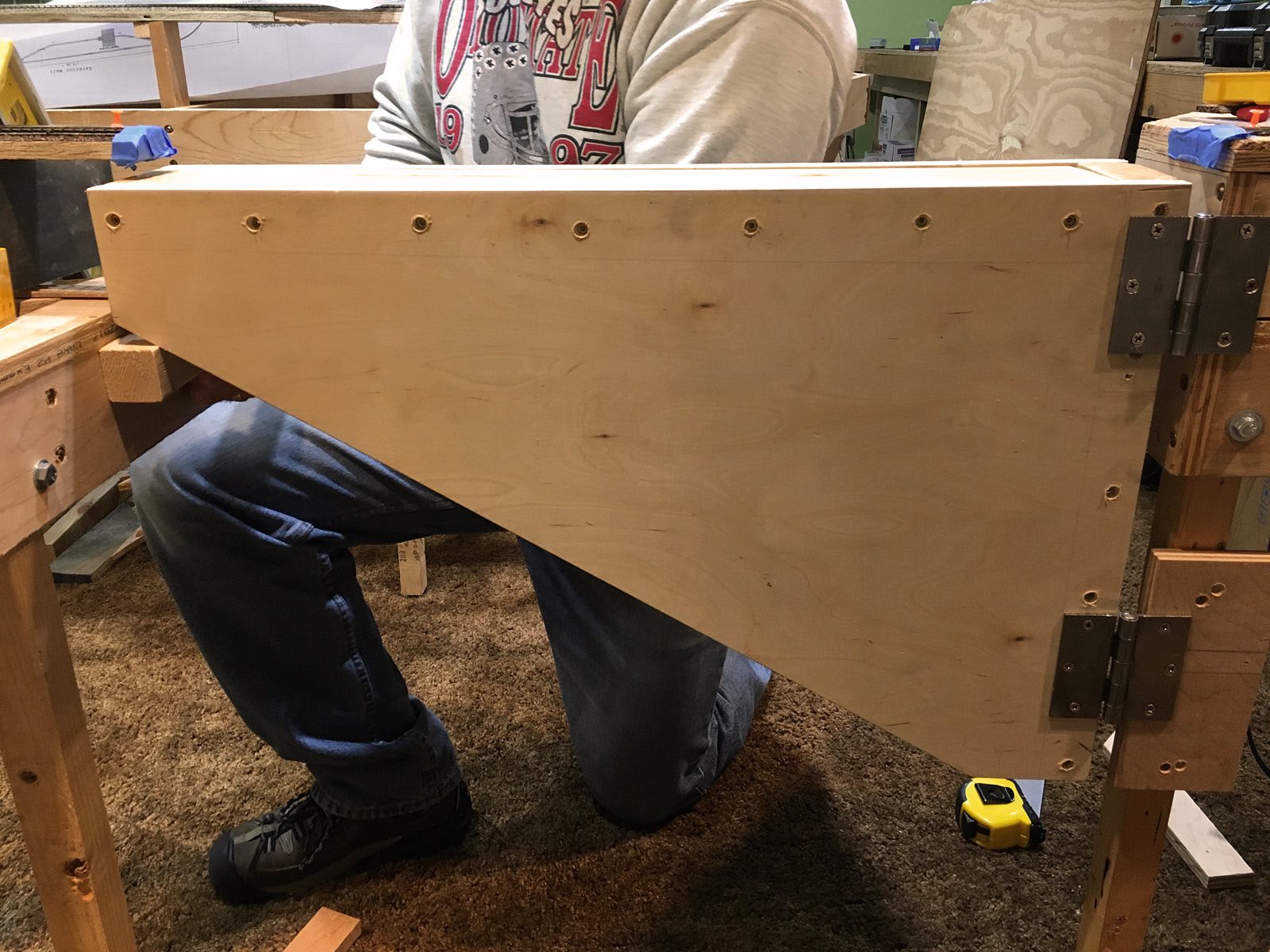
Here is a bottom view of the new wood strip. Screw holes were countersunk so the entire surface will be flat for the Tortoise switch machine. |
|
|
|
|
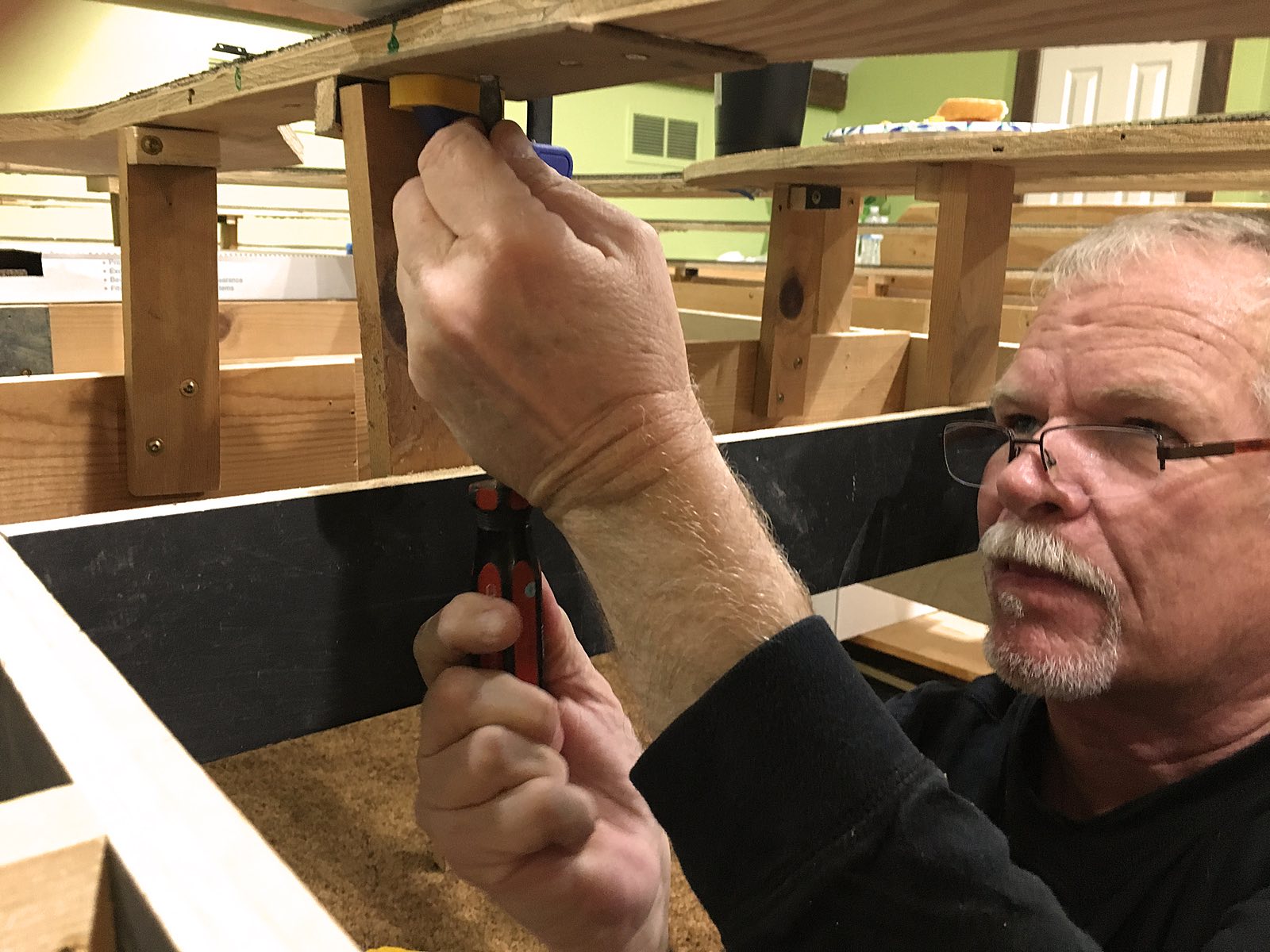
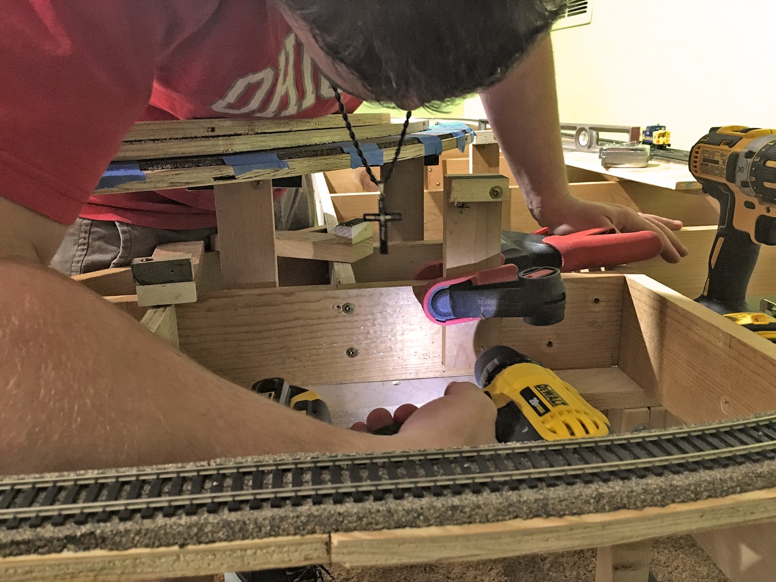
| The greatest challenge for Tom's retrofitting task is the double crossover. He uses clamps to hold the wood in place and then does the necessary body contortions to get underneath the bench work to drive the screws home. Wood, glue and screws come together in award winning fashion. Tom finishes the evening by successfully replacing all problem metal plates. |
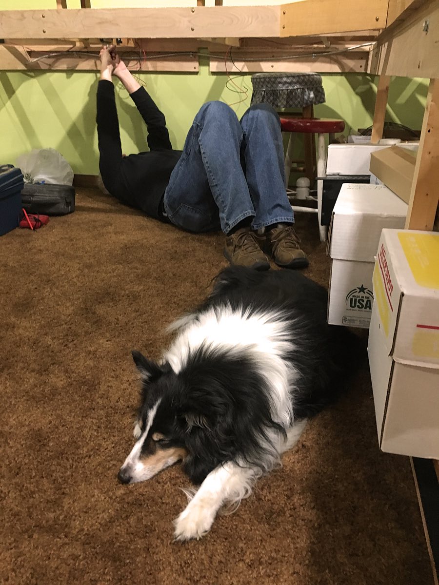
As with any work place some of the folks work hard while others find it siesta time. |
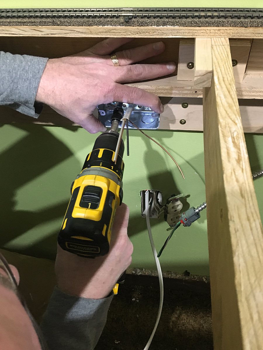
Mike installs the electrical box for the APU power supply run. Fishing the electrical line from the box to the existing outlet proves to be relatively easy. |
|
|
 |
 |
| The box is in place and connected to the APU power conduit. Mike will now connect the new lines to the electrical outlet and put everything back in place. Mike is a great electrician. Of course if he wasn't he'd be dead by now. |
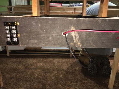
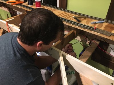
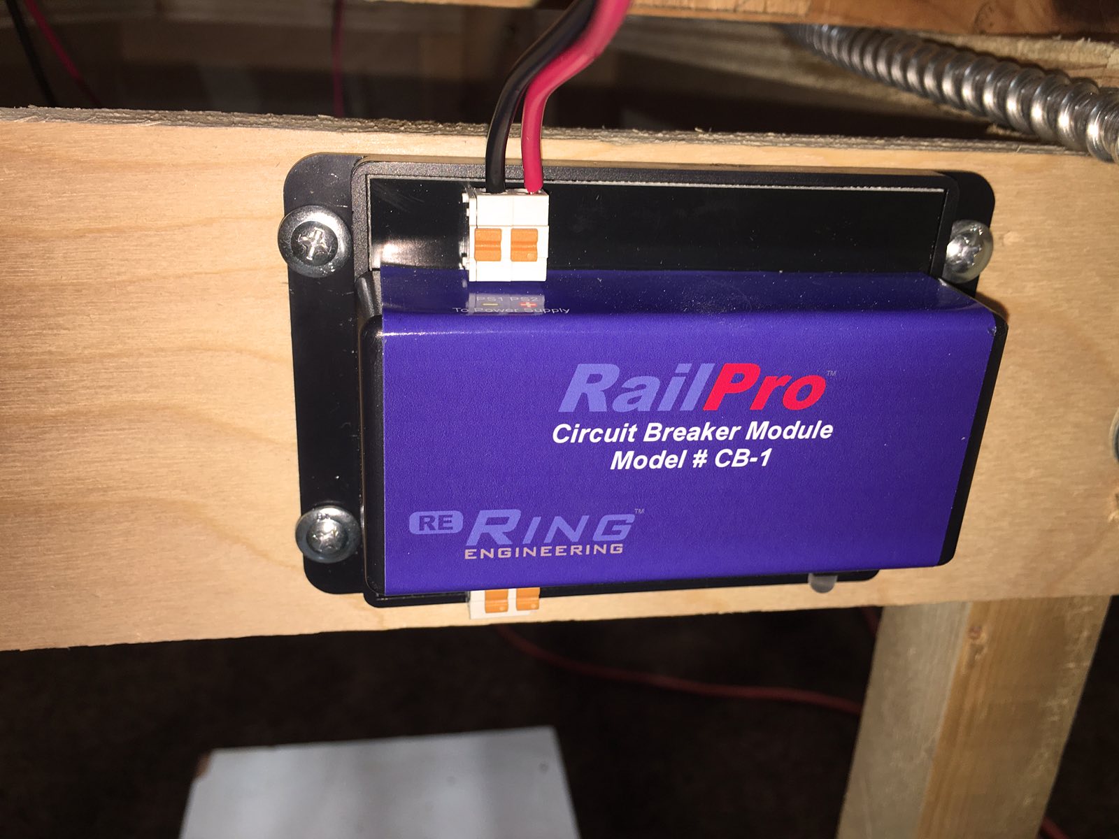
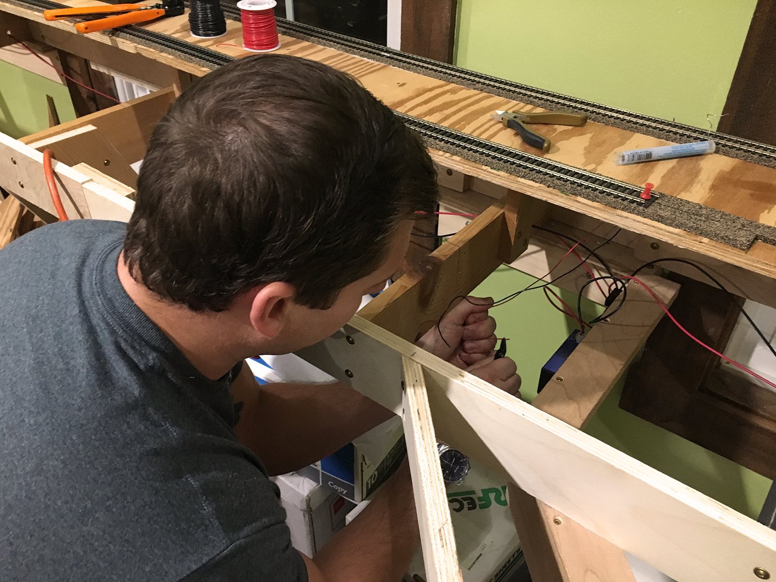
Cracking open a new spool of 16 gauge wire Mike makes the run for the main power bus line. Wires are snaked through the wooden cross member holes LJ created last week. Terminal blocks are used to splice the CB-1s, AR-1 and AM-1s into the main power bus. |
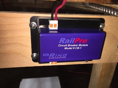
Mike inserts the power lines into each of the six CB-1s and the AR-1. Next week 22 gauge wire will be used to run power from the CB-1s and AR-1to the track. |
|
|
|
 |
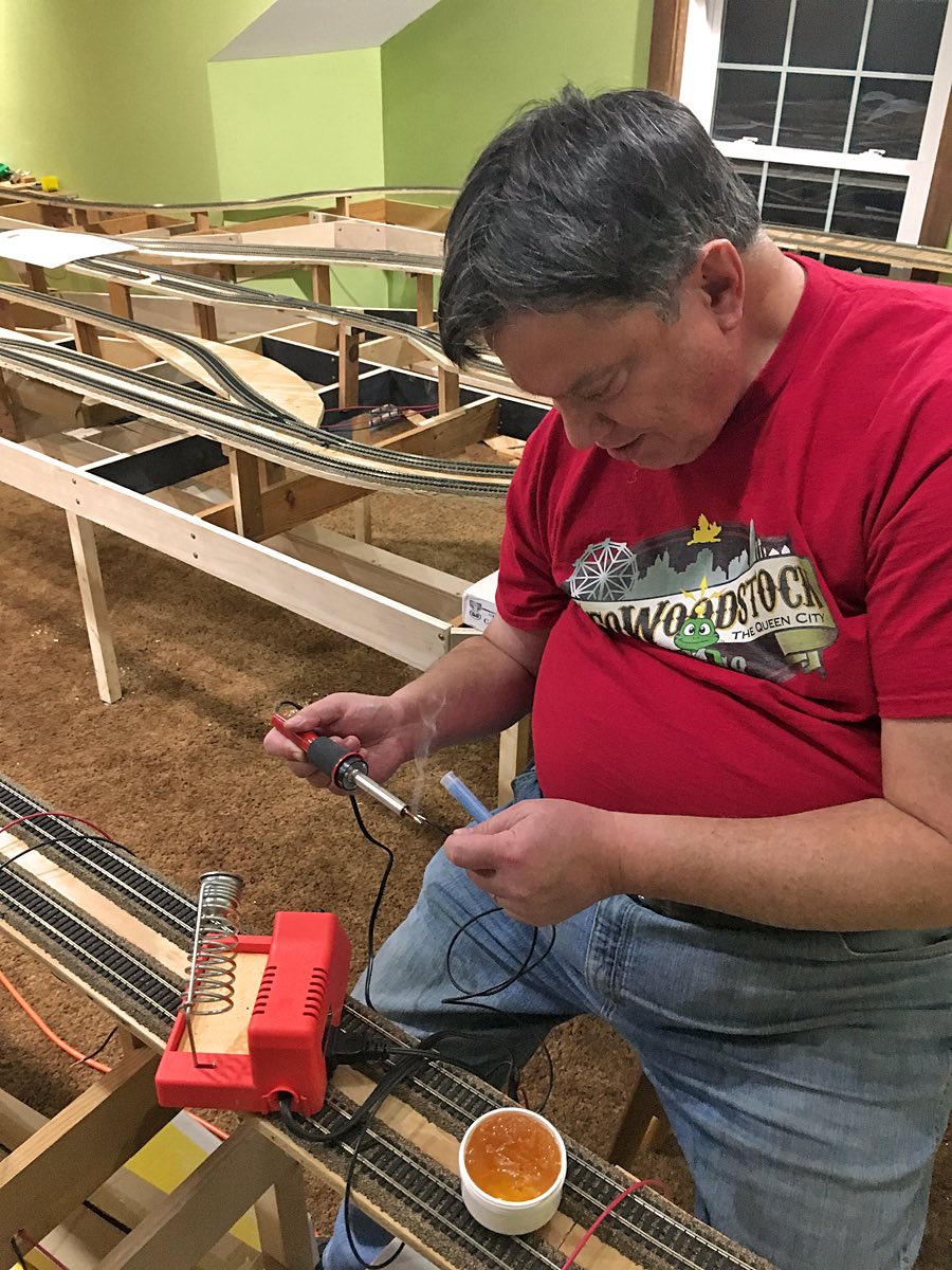
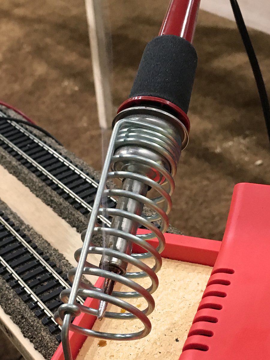
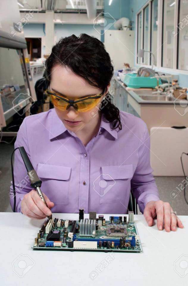
| Last Christmas the CFO purchased a Weller WLC100 40-Watt Soldering Station for John. Tonight he uses it for the first time by soldering tips on all the ends of the power bus lines. |
Although John hasn't soldered anything in over 15 years he was able to pass Tom's test by discovering what's wrong with this picture. Furthermore, John acknowledged his proficiency by stating, "If it smells like chicken then you are holding the soldering iron wrong." |
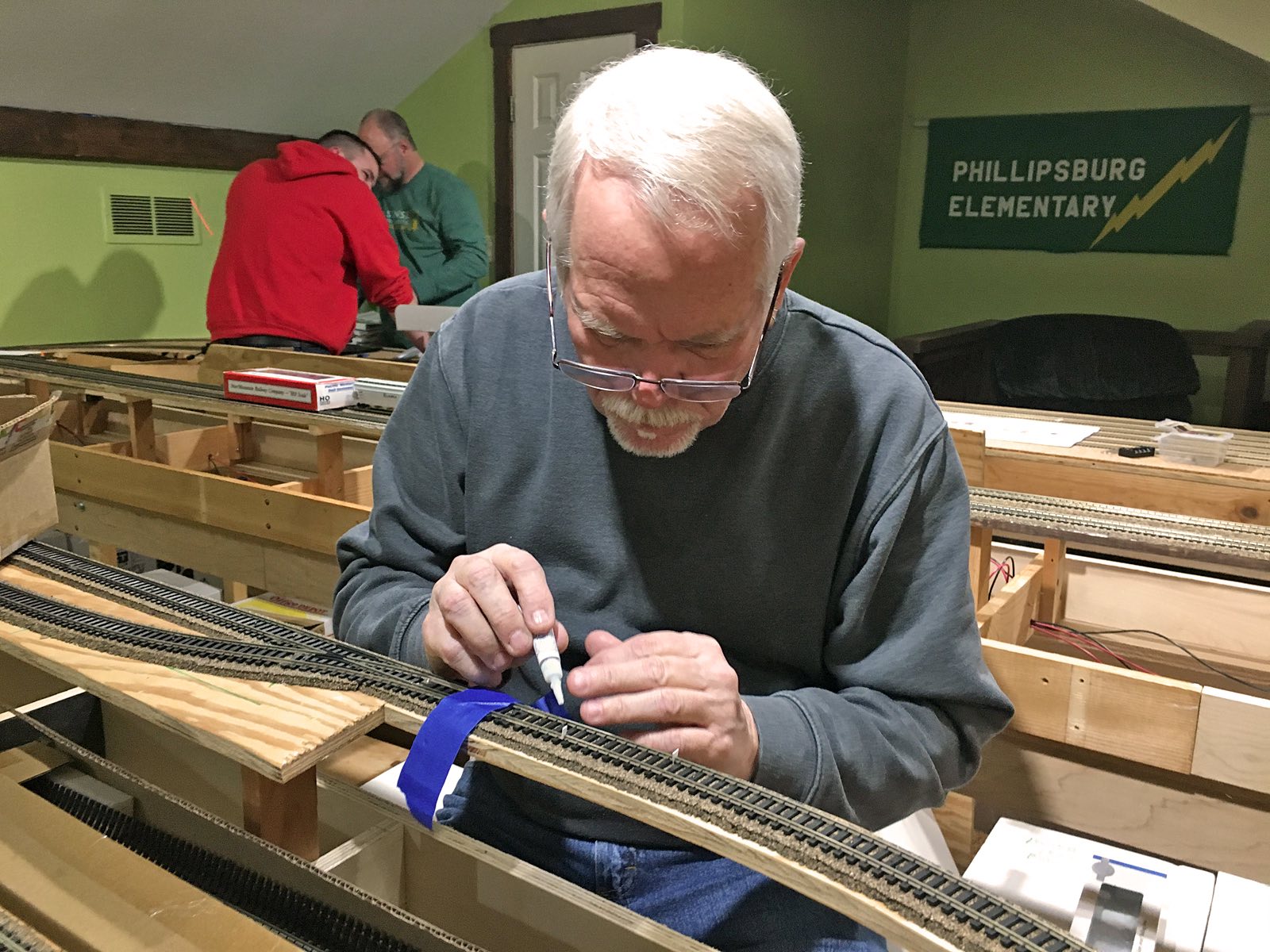
As shown in the December 6th report the entire layout is divided into seven segments. Tom selects the Tunnel Subdivision as a starting segment and makes cuts in the track. He then places small pieces of plastic styrene in the cuts and uses Super Glue to hold them in place. Next week he will cut them down to fit the rail and then sand them smooth. |
December 20, 2018
|
|
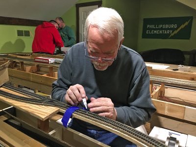 |
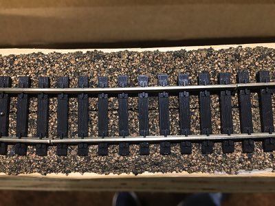
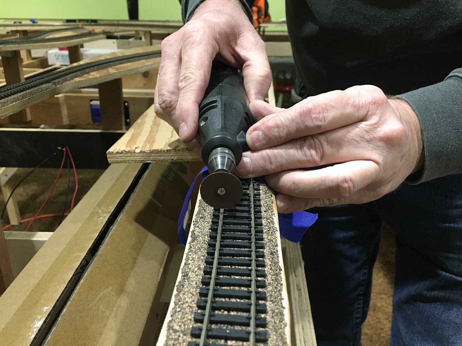
Blocks is the process of dividing the railroad into sections. For the RailPro system this helps to distribute power more evenly as well as narrow down the location of any possible short circuits and other issues. To create blocks Tom uses a Dremel to cut the gaps in each rail of the track. Tonight he cut the rails in six locations to create the final segments. |
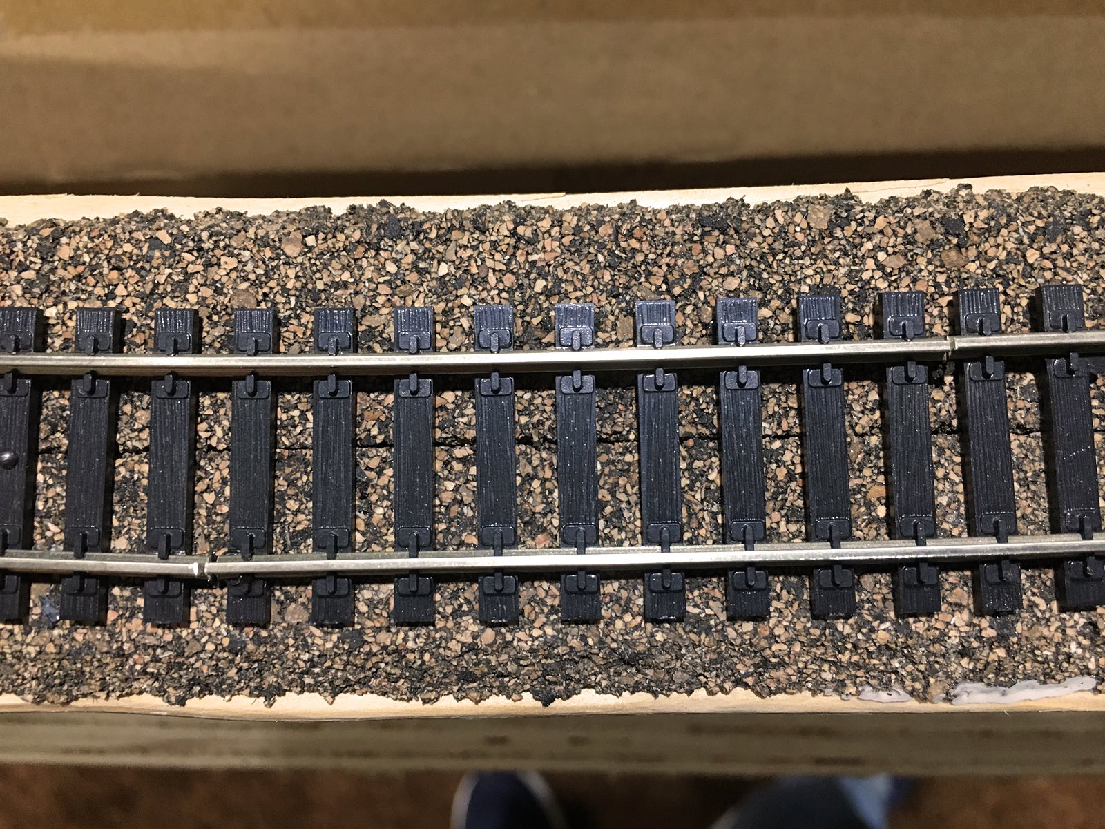
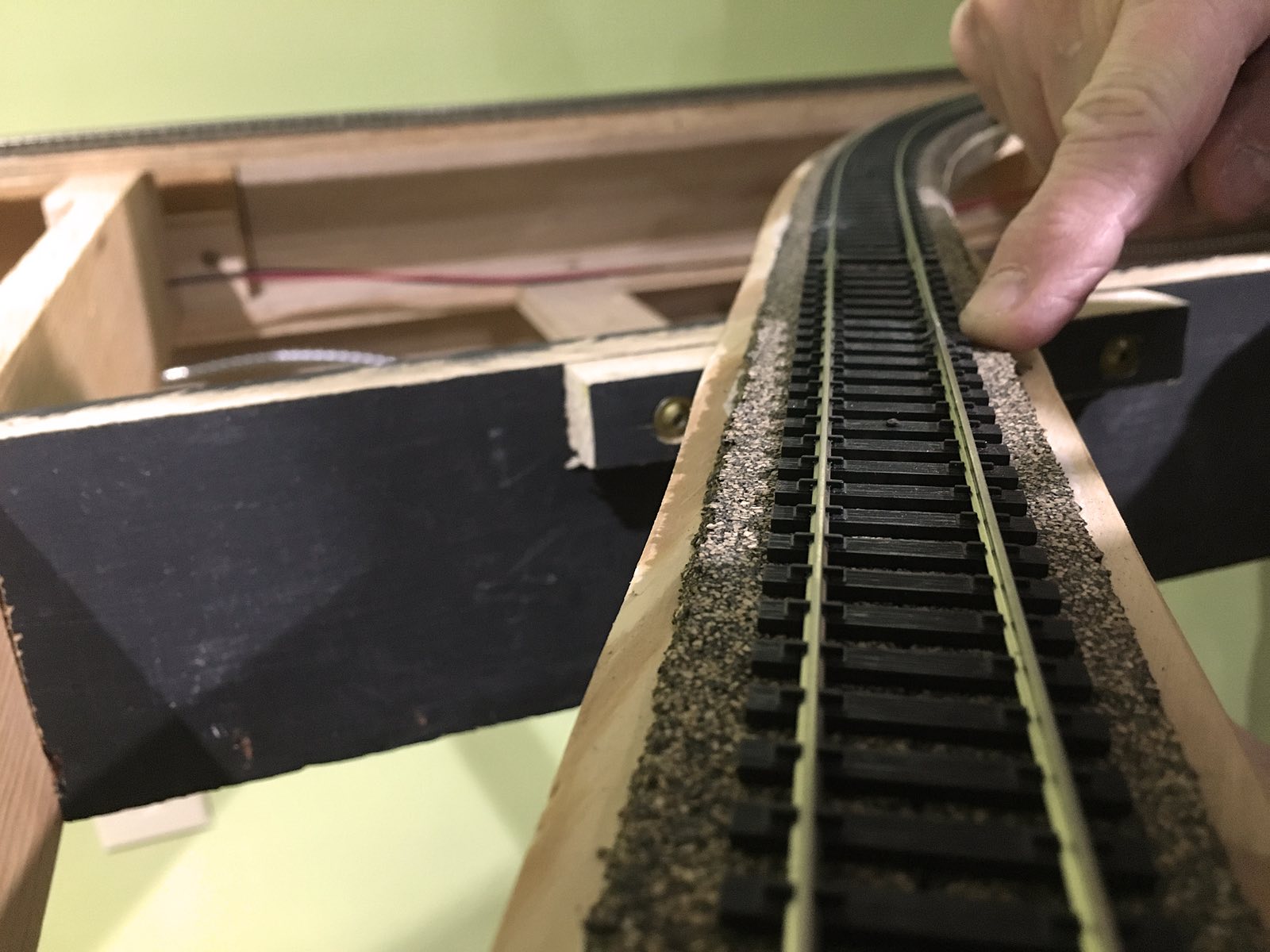
Tom cuts the segments in a staggered fashion to prevent any rail kinking that may occur. |
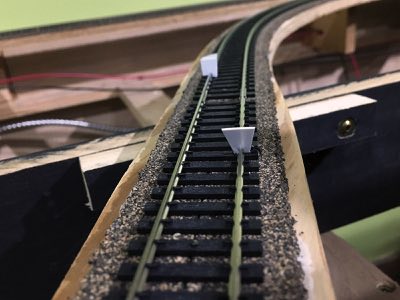
Tom places thin plastic sheets of styrene in the gaps and uses cyanoacrylate (Super Glue) to hold them in place. Once the glue dries Tom cuts then to fit the profile of the rail. |
|
|
|
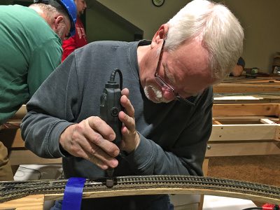
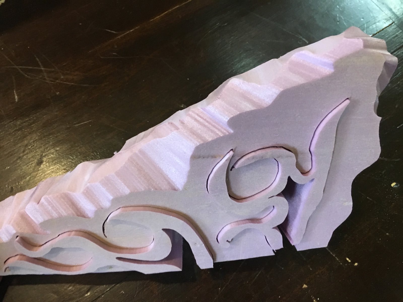
| Using a Dremel sanding head Tom ensures the styrene blends into the profile of the rail. |
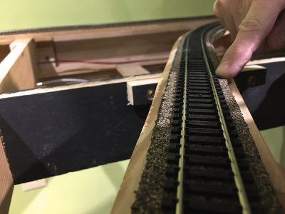
Attention to detail creates a track insulator that is very difficult to see. Once paint is applied the insulator will become invisible. The end result is a sturdy insulator between the sections of track which prevents the potential for rail misalignment. |
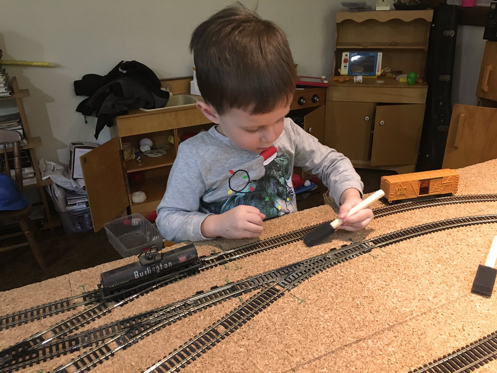
The Golgart family arrives for an early Christmas celebration. As soon as grandson Liam gets to the top of the stairs he wants to assist in our track work. He uses a foam paint brush to help clean the track in preparation for our inaugural run. Two old train cars are there for him to test the track. |
|
|
|
|
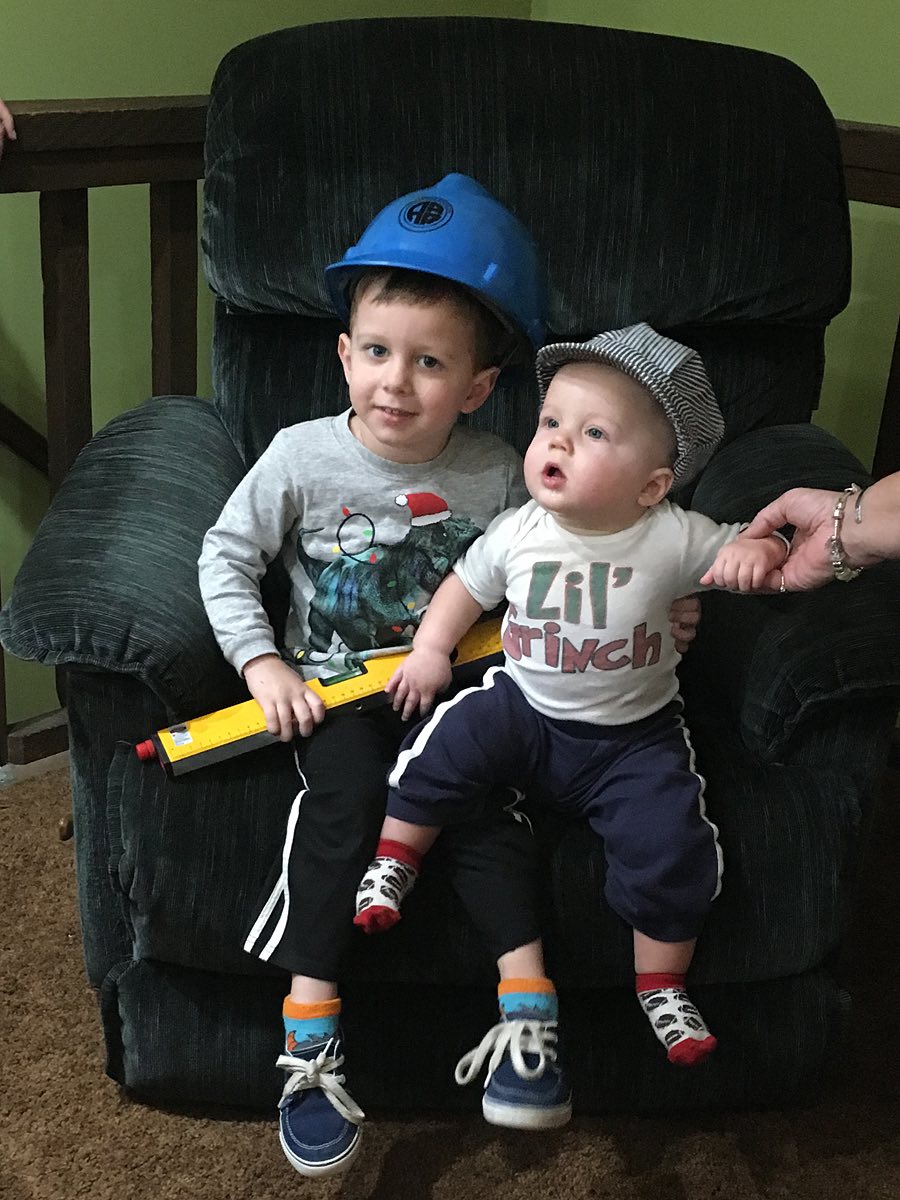
| Donning an engineer's cap grandson Lincoln is ready to run the train. |
Track laborer and train service come together for an evening of fun and frolic! |
Mike and LJ finish connecting all the basic RailPro components. |
|
|
 |
|
For tax purposes John will purchase Tortoises after the first of the year. Each accessory module (AM-1) can handle up to four Tortoises. |
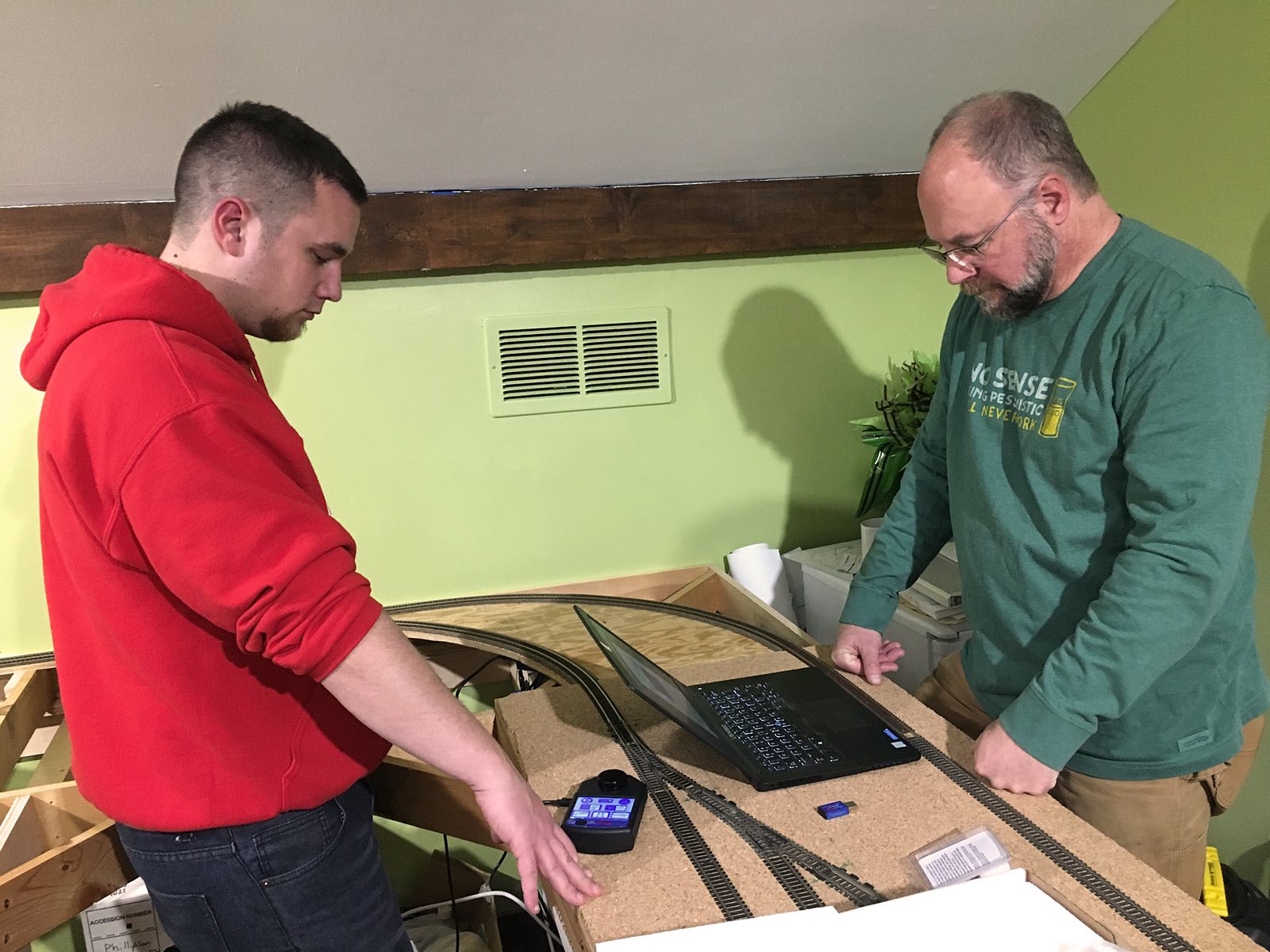
Mike and LJ are boot strapping the RailPro system. All power supplies (PWR-56), segment circuit breakers (CB-1s) and auto reverse loop (AR-1) pop up on the hand throttle (HC-2) as it is powers on. |
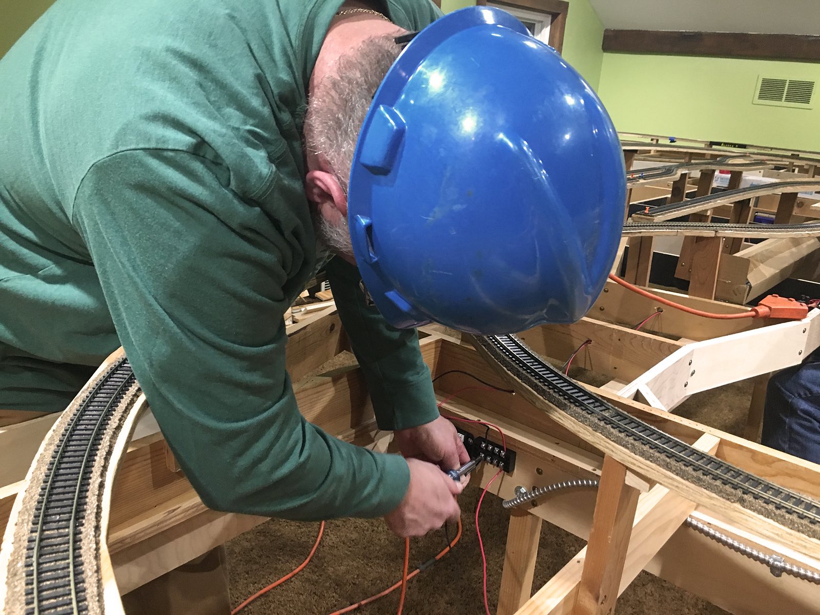
Nick drills the first pair of holes to connect the main line to the CB-1. |
 |
 |
 |
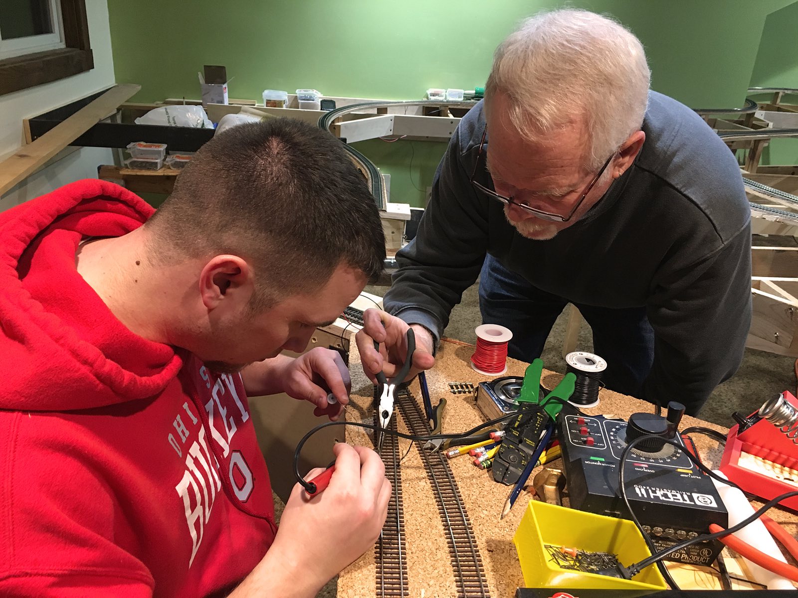
| Nick strips the ends of the wires to connect to the track and the CB-1. |
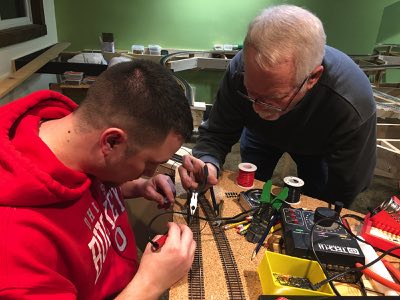
LJ and Tom solder each of the pair of wires to the track. Good connections are a must! |
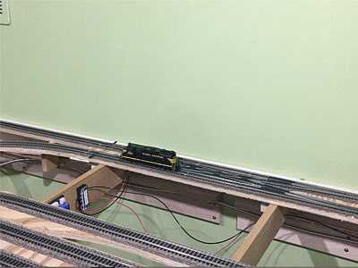
Our goal is to have the train up and running on the main line before Christmas. LJ places a RailPro locomotive module (LM-2) into a DCC ready locomotive. The handheld throttle immediately recognizes the locomotive and the fun begins! Everything works perfectly except for one small section of track. Click on the photo above to view the video. |


